The distortion only occurs when you use FET OPs.
And not when you use bipolar or DIFET OPs.
This is actually not a 100% correct statement. All op amps will produce some amount of distortion in the non-inverting configuration with a source impedance mismatch at the two inputs. For bipolar and dielectrically isolated JFET-input amplifiers it requires a "worse" circuit for the effects to show up.
These effects come from non-linear input impedance and pretty much all op amps have a source of non-linear input impedance, here are some of the offenders:
Bipolar op amps:
- ESD Diode junction capacitance
- Mismatch in ESD diode leakages
- Collector-Base Capacitance (can be mitigated with input stage cascode)
- Beta of input devices varies with VCE (can be mitigated with input stage cascode)
JFET-Input Op Amps:
- ESD Diode junction capacitance
- Mismatch in ESD diode leakages
- Bottom gate to substrate variable capacitance (mitigated in DI processes)
- Gate to source and gate to drain capacitance(can be mitigated with input stage cascode)
CMOS Op Amps:
- ESD Diode junction capacitance
- Mismatch in ESD diode leakages
I've taken A LOT of measurements on this, and come to the conclusion that in the voltage follower configuration, a source impedance mismatch will always degrade performance slightly. The best parts that I've measured so far are our modern JFET input parts (OPA140/141/1641 and OPA827) followed by the older DiFET parts (OPA627, 2107, etc.) followed by bipolar amplifiers with modern CMOS amps close to bipolars (OPA1652, OPAx172).
Some of these measurements (for JFET-input parts) are shown in this article: http://www.ti.com/lit/an/slyt595/slyt595.pdf
Usually all linear ops do not have protection diodes.
No.
These effects come from non-linear input impedance and pretty much all op amps have a source of non-linear input impedance, here are some of the offenders:
No.
Usually all linear ops do not have protection diodes.
LOL. I have a feeling I'd be seeing more customer returns if that were true...🙄
Hi Keruskerfuerst,
At first I thought it pointless to reply to your comment that only JFets have this problem, then I saw that others had addressed the comment rather effectively. Next you decided that op amps don't include any protection for their inputs. Aside from the fact that you are now arguing with people who know for certain, has anything else compelled you to research your statements?
All op amps suffer from common mode distortion mechanisms. Most also incorporate input protection diodes. I say "most" because I am not certain if 100% of them do. This fact has been pointed out in data sheets for many, many years now. All you have to do is read the data sheets completely. Reading application notes is another great free source for education. Take advantage. This information took these manufacturers many years and tons of money to produce them. Don't waste that resource.
Thank you John for your view from inside the industry. You are living through a time when a marked jump in device capabilities has occurred. The acquisitions of National and Analog Devices have made TI a real powerhouse. Must have been a really cool time for applications engineers. I hope you took some of those early devices home to play with!
Best, Chris
Hi Chris,
Thanks for your response. Just to clarify TI did not acquire Analog Devices. I'm pretty sure if Scott Wurcer reads that he'll spit out his drink on his computer 😛 TI only acquired National. Analog Devices DID however recently acquire a really cool company called Hittite Microwave.
Back to op amps. Most, and by most I mean 99.99%, of op amps have ESD protection structures on the inputs. I believe early-on some amplifiers intended for extremely low current instrumentation (electrometer type work) removed the ESD structures to further reduce input bias current. However I can't think of any part numbers at the moment. Most low input bias current op amps still have ESD protection (OPA128/129, INA116, LMP7721 and the other ridiculously low input bias current devices from National).
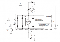
And yes, we show the input ESD protection scheme in most of our datasheets, here's an example from the OPA1611/1612 datasheet:
Attachments
Hi John,
I remembered when the TL072 came out. It was a stand-alone clear cut winner for sound quality and input noise. The first time I saw them was in a French made little mixer for DJs. I replaced a ton of 1458 based stuff in my equipment with the TL072 and instantly upgraded their performance. I've used most of the newer families in various applications and the current level of performance is amazing. "You" done good!
I am familiar with Hittite, but have never used their HF stuff before. I am working with L1 and L5 GPS stuff now, so I'll bet they have some very interesting solutions.
John, would it be fair to say that most op amp input damage is actually shorted input protection diodes as a failure mode? Not that it really matters as everything is unreachable to the average person. Better input protection fails than the input stages as the protection will take more abuse before going short. Input stages would tend to become noisy along with an unmatched pair if protection wasn't there and there wasn't a total failure.
-Chris
Oops, yes. It was Burr Brown that TI acquired. I could have edited my error (figured you would call me on it), but when I post as a member, I try to be subject to the same rules and limitations.Just to clarify TI did not acquire Analog Devices.
I remembered when the TL072 came out. It was a stand-alone clear cut winner for sound quality and input noise. The first time I saw them was in a French made little mixer for DJs. I replaced a ton of 1458 based stuff in my equipment with the TL072 and instantly upgraded their performance. I've used most of the newer families in various applications and the current level of performance is amazing. "You" done good!
I am familiar with Hittite, but have never used their HF stuff before. I am working with L1 and L5 GPS stuff now, so I'll bet they have some very interesting solutions.
John, would it be fair to say that most op amp input damage is actually shorted input protection diodes as a failure mode? Not that it really matters as everything is unreachable to the average person. Better input protection fails than the input stages as the protection will take more abuse before going short. Input stages would tend to become noisy along with an unmatched pair if protection wasn't there and there wasn't a total failure.
-Chris
I don't know that I'm qualified to say that shorted protection diodes are the most common failure mode. And I would bet it varies product-to-product. Our quality engineers would be more apt to answer that (versus an applications or systems engineer) just because they're the ones that de-cap the part, look at the die, and figure out where it all went wrong. Then they report back to the customer on the failure mechanism.
Hi John,
Fair enough. I was just trying to imagine the most likely failure mode in my mind. Just casual interest as my own background is equipment service and designing modifications to solve problems.
It would seem to me that the application engineers should hear about failure modes as well. It is your job to assist the customer in coming up with a circuit design in the first place.
I'm going to stop talking shop with you now as we are way off topic. Thanks for your answers.
-Chris
Hi George,
Thanks for the hint with AD825. In principle the unity gain buffer PCB that I plan to design can use both LME49990 and AD825 because they have the same package. This could be something to try but as I stated earlier I will not be able to decide based only on listening test and I am not ready to invest into an expensive measuring tools.
I do think that the circuit for audio reproduction should have no sound coloration in any way. If someone wants to "color" the sound in the way he likes it is always possible to do with the dedicated device giving full control of the situation.
This is why the op-amps with the distortion figure beyond fourth digit after comma are very attractive to me (LME chips). While AD825 datasheet seems to only provide data relevant for high frequency (MHz range) applications and nothing related to audio range... And I personally have very limited knowledge of parts on my own. So if you could point me where audio range related data for AD825 is discussed it will great.
Regards,
Oleg
the AD825 12 nV/rtHz noise is speced at 10 kHz - datasheet writers only do that when the 1/f corner is over 1 kHz - and 12 nV is already poor, expecting several times that at 1 kHz is worse for audio
I wouldn't get too carried away with specs, the AD825 to me just sound right, uncoloured with plenty of drive and transparency (just make sure it's stable in your circuit).
Remember poweramps that have great specs with heaps of global feedback, they don't sound as good as the same thing done with local feedback that don't measure so well.
One opamp that has good measurements (probably better than the AD825) is the OPA627 which to me sound way too dark and coloured, tube lovers may like it.
Cheers George
Last edited:
Thanks for the hints everyone!
I went further with my idea and found a pair of complementary pos/neg regulators to be placed right next to the buffer op-amp: TPS7A4901 and TPS7A3001. Could someone please comment on their suitability for the task or suggest alternatives? I'll feed them from the standard LM317/LM337 regulators combo to minimize the stress on them.
The regulators are really small but not impossible to solder by hand. I also have a heat gun so may try it too.
Regards,
Oleg
Thanks for the hints everyone!
I went further with my idea and found a pair of complementary pos/neg regulators to be placed right next to the buffer op-amp: TPS7A4901 and TPS7A3001. Could someone please comment on their suitability for the task or suggest alternatives? I'll feed them from the standard LM317/LM337 regulators combo to minimize the stress on them.
The regulators are really small but not impossible to solder by hand. I also have a heat gun so may try it too.
Regards,
Oleg
Those are pretty decent low-noise regulators. I have used them before with good results. One recommendation I have is to follow the applications information in the datasheet for choosing resistor and capacitor values. Otherwise they can oscillate (as can all adjustable regulators).
Since these have a thermal pad you may want to use the heat gun and some solder paste.
It is a small heat gun from Proxxon (called "MICRO Heat Gun MH 550"), not a dedicated soldering station. It has two stages. The first gives 350 degrees Celsius and the second gives 550 degrees Celsius.
Oleg
Oleg
Hi Oleg,
Practice on something else first. Your heat gun sounds like it is intended for heat shrink tubing.
-Chris
Practice on something else first. Your heat gun sounds like it is intended for heat shrink tubing.
-Chris
Hi Conrad,
I'd like to see at least 6 dB. Tone controls would force another 10 dB or so, and that's okay.
No matter what, you have to live with the unit, and there is a fair amount of background noise to deal with. Not many of us will approach a 70 dB S/N in truth, so don't sweat absolutes.
-Chris
I'd like to see at least 6 dB. Tone controls would force another 10 dB or so, and that's okay.
No matter what, you have to live with the unit, and there is a fair amount of background noise to deal with. Not many of us will approach a 70 dB S/N in truth, so don't sweat absolutes.
-Chris
I am designing a PCB with the possibility to use it in the inverting and noninverting configurations with gain which will allow me to use it in different ways depending on the situation. I'll post a schematic with the PCB draft in the next days.
Oleg
Oleg
Asking about gain because whenever I've added a line stage to my passive preamp it's always got too much gain, and I end up pulling it out. 6 dB makes sense and I doubt I'd ever need more than that. IMO, it's easier to build a fast high gain stage than unity.
- Status
- Not open for further replies.
- Home
- Source & Line
- Analog Line Level
- Line level buffer: discrete or ICs based?