
It is vector program, so that's fine. Problem is when exporting to pdf but print shop can open dwg and print, actually plot, directly. Thing is printer head moves left and right, at 45 degrees I will get worst pixelization, but let's see how it turns out...
I've used AutoSketch for DOS (baby brother to AutoCAD). Use the ring array command to divide the circle into the number of bars you need, then arc mode on the inner and outer circles to define a bar. Fill it with black, then remove all the construction lines and use the ring array function to copy the single bar round. Your might want to check how AutoCAD is talking to the printer to make sure it does what you expect, but I got acceptable results even on a 300dpi printer.I did some trials, printers don't really like angled lines, always got bit of zig zag effect under magnifier... You think it's worth putting effort?
Than I also need to decide paper quality as it's crucial
I tried to measure speed accuracy dirt, cheap and fast , just as beginning..
My wife has iPhone 11 with gyroscope, I downloaded this app: https://apps.apple.com/us/app/turntable-speed/id1604670976
And this is result:

Not that I trust it too much , it is just indication that thiongs are not too bad 🙂
My wife has iPhone 11 with gyroscope, I downloaded this app: https://apps.apple.com/us/app/turntable-speed/id1604670976
And this is result:
Not that I trust it too much , it is just indication that thiongs are not too bad 🙂
🤣 first I need to install tonearm, cart and preamp to see how it sounds, right now it is just numbers and secondary noises.If it sounds OK on piano, it's probably OK.
But to comfort, year ago with much worst numbers and noises, piano, strings and cymbals sounded quite ok
Hi, I use NanoCad now as it is last left to be free, before using DraftSight, and before, for work, Autocad. All 3 seem to be very similar.I've used AutoSketch for DOS (baby brother to AutoCAD). Use the ring array command to divide the circle into the number of bars you need, then arc mode on the inner and outer circles to define a bar. Fill it with black, then remove all the construction lines and use the ring array function to copy the single bar round. Your might want to check how AutoCAD is talking to the printer to make sure it does what you expect, but I got acceptable results even on a 300dpi printer.
Made 360deg strobe quite easily, see pdf (with note that pdf has raster, print sample directly from .dgw or .dxf is very nice).
Short instruction how to do it:
1. Make center point, 2 crossed lines 90deg extending strobe size
2. From that center point draw 2 circles, inner and outer limits of strobe.
3. While in ortho, make 1 line inbetween circles and exactly over one of center lines. Calculate circumference of strobe and divide by number of strobe points and than divide by 2: that is that short line thickness. (to ensure equal black and white spots). Mine is at 260mm diameter, 360 points, line thickness 1.2mm.
4. Select that line and go to modify - array - polar array
5. Here select center point in center of circles, Total number of items : #of strobe points, Angle to fill : 360 deg click ok and whalah!
6, trim extra lines so they don't interfere
Let me see how will it work with print shop, but looks promising.
Attachments
Printing and gluing of strobe on platter actually went very good. Nevertheless new problem arises; I think I pushed CNY70 sensor beyond its physical dimension limits with 1.2 mm strips of black. Resulting signal is more like mV sine wave instead of full range square, and full with noise and oscilations. I will try to amplify it and than schmitt trigger it. Alternative is to reduce number of points from 360 to 270 or 180. Ill see, it is work in progress...

Strobe disc looks good. If I've done my sums correctly, you should be producing a 200Hz square wave at 33 1/3 rpm. For a useable shape, you'd need to recover the 5th harmonic, so that's 1kHz. What sort of a sensor is so slow that it can't reproduce 1kHz? You do have a <1mm slit in front of the sensor? If you don't, you will be averaging black and white bars together...
Hi,
Ill rotate the sensor, Ill see.
The sensor is not too slow but it is too large physically, i think, Light is illuminating both black and white at the same time, and photo transistor is also receiving both, that's why I get small AC signal sine wave, again I think.
On supaspin tach, where I have just one large black spot, signal is sharp way up on leading edge, perfect for measurement.
Hi,
I rotated sensor for 90 deg, it is still miserable signal full of noise and harmonics. Nevertheless something shows very nice, I zoomed 200Hz at spectrum analyzer and frequency dance left and right is almost gone. Regardless of noise it seems it is picking right pulses at the time. Here is short video. When I was playing the same trick with test LP, left and right speed dance was much worst.
I rotated sensor for 90 deg, it is still miserable signal full of noise and harmonics. Nevertheless something shows very nice, I zoomed 200Hz at spectrum analyzer and frequency dance left and right is almost gone. Regardless of noise it seems it is picking right pulses at the time. Here is short video. When I was playing the same trick with test LP, left and right speed dance was much worst.
I played a bit more with phone app, same setup as described above in post #224 and found something interesting:
Since this app is free and seems to be very sensitive, at least with my wife's iPhone 11, I encourage anyone to try and comment, its so easy and fast
- with really tight belt, tight enough to physically increase drag, I consistently get RMS WOW of 0.04 - 0.05% at 33.33 and 0.03 - 0.04% at 45 rpm, this is world class result.
- with little bit longer and softer belt, that by the way looks perfect for eye, I can get best 0.13% WOW, Normally 0.17%, 0.2%...
Since this app is free and seems to be very sensitive, at least with my wife's iPhone 11, I encourage anyone to try and comment, its so easy and fast
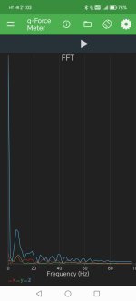
Another phone app I started to use and compare, this time vibrations at plinth . App is called Physic toolbox suite and inside is G-force meter.
I applied very strong knock with my finger at plinth, good enough to knock tonearm out in space. First picture is just acceleration showing that all settles back within 0.5 seconds.
Second is the same in FFT, showing relevant frequency of 4-5 Hz.
I did same with Linn Sondek (but much more gentle knock as this one is delicate) frequency was 10 Hz or about, settling time 2-3 seconds.
This is also easy one to try if anyone wants. Lower frequency and shorter settling time is better I think...
Attachments
That's really surprising. You'd expect a looser coupling to the mass of the platter to be better. But if your measurements are right, that's not the case. You've used a really good motor and driven it properly, suggesting that its rotation ought to be correct. So your result is suggesting that a major cause of wow is actually slippage between the belt and the motor pulley (I think we can probably discount slippage on the platter). Conventional wisdom has been that flat belts are superior to round belts because they enforce a constant ratio between the pulleys, but what if they actually have lower slippage? And would that explain why idler drive sounds good? Interesting stuff.So 4-5 times improvement by tighter belt...
- with really tight belt, tight enough to physically increase drag, I consistently get RMS WOW of 0.04 - 0.05% at 33.33 and 0.03 - 0.04% at 45 rpm, this is world class result.
- with little bit longer and softer belt, that by the way looks perfect for eye, I can get best 0.13% WOW, Normally 0.17%, 0.2%...
Fit a slit to your optical sensor. A bit of black paper with a narrow slit ought to do the trick.
Brilliant, I'm bit ashamed it did not come to my mind, thank you.Fit a slit to your optical sensor. A bit of black paper with a narrow slit ought to do the trick
For belt and wow, it is first time I'm conducting such tests with instruments, so take it with reserve.
Nevertheless I could replicate measurements few times, and long time ago decided on tighter coupling based on listening. It sounds, well, tighter
I did cover optical sensor with black tape, and left just tiny slit opened.
Signal is still very poluted, I see my problem now. All wires are opened in the air and picking up 50Hz and all its harmonics stronger than signal from sensor.
Unfortunately my chosen measurement frequency is 200 Hz, a harmonic of 50 Hz. To separate signal and 50Hz noise, I measured peaks while changing speed from 33 to 45. Now it is clear what is what. Signals that stayed at same place are noise, signals that moved to new frequency are measurement signals.

It is a bit puzzling still that I dont get measurement signals at expected frequency. But as said, it is work in progress.
Than I picked one at 480 Hz that was strongest and definitely not related to mains noise but to sensor output. Very pleased that speed dance is very very small. This is at 45 rpm
I have to shield all my connections to reduce noise, thats homework...
Signal is still very poluted, I see my problem now. All wires are opened in the air and picking up 50Hz and all its harmonics stronger than signal from sensor.
Unfortunately my chosen measurement frequency is 200 Hz, a harmonic of 50 Hz. To separate signal and 50Hz noise, I measured peaks while changing speed from 33 to 45. Now it is clear what is what. Signals that stayed at same place are noise, signals that moved to new frequency are measurement signals.
It is a bit puzzling still that I dont get measurement signals at expected frequency. But as said, it is work in progress.
Than I picked one at 480 Hz that was strongest and definitely not related to mains noise but to sensor output. Very pleased that speed dance is very very small. This is at 45 rpm
I have to shield all my connections to reduce noise, thats homework...
Not just shield, but twist the conductors together to reject magnetic fields as well. It should be possible to get a nice clean signal. Even at 200Hz.
Not just shield, but twist the conductors together to reject magnetic fields as well. It should be possible to get a nice clean signal. Even at 200Hz.
For that a good shielded two conductor audio cable should work.
- Home
- Source & Line
- Analogue Source
- Limestone turntable, help needed with motor and drive