Well said tinitus.
Are these devices perfect? No! is anything: No!
Is there work involved: Yes, a lot when you go matching.
Also, just so people are aware, there can't be much return in this for George, or Uriah either. I don't see that either of them are planning to retire to the Bahamas on the $$ they will be making from LDRs! Its up to an individual themselves whether you want to make one or not.
Fran
Excuse my ignorance (newbie must start somewhere) but IF (and I stress if because I have no idea) there is a concern with "drift" or other variations could this not be reduced by multiples in parallel? (ummm NO is a suitable answer BTW.)
There is no concern with drift, my prototype MKII is now over 5 years old and has been powered 24/7 for those 5 years and the NSL32SR2S are still in perfect match, thats 44,000hrs and still pefect in channel balance from zero to full volume. But your idea of paralleled series and shunt would give a lower min volume, which could be good for those who have 100db speakers.
Cheers George
Cheers George
Thx. Sorry George... I was just flipping through quickly and noticed (1 person in particular) talking about their concern.
Excuse my ignorance (newbie must start somewhere) but IF (and I stress if because I have no idea) there is a concern with "drift" or other variations could this not be reduced by multiples in parallel? (ummm NO is a suitable answer BTW.)
NO - cause more LDRs you need, more troubles with matching you are after
i think the only way to keep these resistors within certain tolerances is to change the way how they are being driven - there should be a circuit to measure their performance in real time and immediatelly correct their resistance so L and R output are matched.... and it's not about "drifting" over time, which is another issue mentioned here, it's about impossibility to match them across the whole audioble spectrum and at all the atenuation levels.
but i have no clue how this is to be done....
i actually think we are all being misguided into a paradigm of "matching" while no one thinks in a different direction - let the LDRs be unmatched but find a way how to harmonize them in real time
Hornperfect.... Why are you assuming that George or I would screw people over? I really dont understand that line of thinking. I make money on matching them but my ethics would NEVER allow me to sell something people do not need, nor to convince them that the do in fact need something that they dont.
There were 120 from numbers 121-240 tested recently. Here is a copy of the first two matches
220 .2265k 1.479k 2.704k 4.918k
153 .2192k 1.468k 2.741k 5.060k
and here is the last two matches
228 .2872k 4.061k 9.119k 19.796k
123 .2830k 3.898k 8.921k 19.945k
Do those look real close? I mean if we were to use number 228 and number 220 as series you would never get them to act the same. Thats what would happen if you just dip randomly into a bag of LDRs and pop them in your circuit. You can use dual pots to adjust left and right but your impedance will never be close to equal. Build it that way if you want. No one ever tells anyone they cant do that but we do point out that it will sound different and at certain extremes and amp input impedance situations it could put undue load on your source.
I am not being dramatic about this but its honestly a little saddening to think that you have this real feeling that George or I are trying to misguide people. Thats not our goal. The goal is to get LDRs that work correctly and in cooperation with each other into peoples systems so that they can hear how incredible the LDRs are. I dont understand the animosity and doubt.
You want to 'harmonize them in real time?" Yeah you can do that. There was a discussion about Myth Audio recently. Thats what he does. Well not exactly but they are matched by DAC/ADC/MicroProcessor before put into use. To measure them while in use you need to be able to measure current and/or voltage without tapping into the line. Its possible but not at this low of a scale for anything affordable. You use current or voltage sense transformers etc with higher currents and voltages. The other way is to tap off the line and rectify the AC current then measure it and change the LDR and then measure again at the same time you need to know the exact measurements of the AC signal coming in before it was DC.. Why is matching not the best solution? Its the cheapest solution as I sell them for less than it would cost to buy enough for the average batch of LDRs to produce a good quad and I take the work out of it. Do you have any idea how many grateful emails I get from people? Or the huge undertaking it is every time I go to start matching? I also walk everybody who needs it the entire way through their Lightspeed build. I dont leave them there wondering how to do it or embarrassed to post online. They get my support, it gets built, they hear how wonderful it is. And here you are with nothing to do but doubt and bash. I dont get it.
Uriah
i respect your stance of LDRs as a very cost effective solution, that's true.
More than 50 dollars for a set of 4 LDR's (including shipping) for 1 volumecontrol is not cheap in my book. Anybody can decide for himself if it is worth the money, but it is no bargain.
So if you sell them at this pricelevel you should not have an attitude as if you are doing the world a great favour, you are just doing business (which is not illegal of course 🙄 )
OK -.....
and - what's really a point ?
not to take water on my own watermill (that mill is small anyway) , but I must say few words - LDR based attenuator is - under known conditions (preceding and following impedance , normal line signal levels) certainly better sounding than many of more expensive solutions . 200++E TKD 4 deck pot is certainly waste of money , compared with this type of attenuator .
every drek have it's own flaws ; you mention TVC/AVC as other type of attenuators as obviously flawed ......
in same time - you said that you have idea what's needed for better function of LDRs ,calibration etc ...... so you obviously didn't follow this thread from beginning . ppl already had that idea , few certainly made own solutions .....
so - either contribute with your solution , or leave these kids alone in their playground .
they like LDRs ; with few additional parts they're singing -and - price comparable - two Black Beauties are rip off , if you make comparison .
Stupid LDR matching question...
I'm trying to understand the works of LDR matching and I always get confused with the dB unit....
At the same current over the LED (let's say 2.5 mA or simply I) two different LDR's will display different resistance (let's say 280 and 300 ohms or R1 and R2). What is the formula for transforming the difference in resistance into dB units?
I know I could work it out myself by studying a bit, but I'm sure that some of you friendly guys could tell me in a millisecond🙂
Thanks,
Nic
i can write about it - do you want that? better not - rather go and read thorsten's thoughts which are spot on. but than he is not only a designer (and a DIY-er) but a listener too.
Preference is a matter of preference. It's not an absolute. So, if you don't prefer to use an LDR (personally, I don't, either), then move on, you've made your point. Unless you have something new to contribute, in which case, we're all ears.
.......
i anyway don't expect this post to last very long, thanks, just as any other that shows different opinion. kudos to freedom of speech on forum.
dunno for that , but - regarding LDR vs. any other - I can tell you that I like more AVC or - even better - TVC than LDR att.
and I just don't care which one is more linear , I know what's more amusing for my ears .
so - to each his own ; considering that you're only one here capable to hear these frequency anomalies , make your own solution and present to all ignorants .
or , at least - present these tests of yours , where you measured F. anomalies in LDR attenuators .
The only way one can use non matched ldr's is to have some way of constantly measuring the resistance in real time while playing music through the them, (because as with all cd's/tracks we want different levels of volume), this in itself is a problem of added corruptions from microprocessor or any other type of resistance monitoring devices.
The only thing in the signal path is one resistor when built with a matched sets of NSL32SR2S ldr's as set out from the start of this thread. This is what/why the Lightspeed Attenuator is all about.
Cheers George
The only thing in the signal path is one resistor when built with a matched sets of NSL32SR2S ldr's as set out from the start of this thread. This is what/why the Lightspeed Attenuator is all about.
Cheers George
i anyway don't expect this post to last very long, thanks, just as any other that shows different opinion. kudos to freedom of speech on forum.
Why do you continue here
Theres a perfectly good thread better suited
Theres even good skilled members there
Nothing wrong with the freedom of speech
http://www.diyaudio.com/forums/analog-line-level/159163-optocoupler-attenuator-preamp-general-2.html
No more warnings

I'm trying to understand the works of LDR matching and I always get confused with the dB unit....
At the same current over the LED (let's say 2.5 mA or simply I) two different LDR's will display different resistance (let's say 280 and 300 ohms or R1 and R2). What is the formula for transforming the difference in resistance into dB units?
I know I could work it out myself by studying a bit, but I'm sure that some of you friendly guys could tell me in a millisecond🙂
Thanks,
Nic
or , at least - present these tests of yours , where you measured F. anomalies in LDR attenuators .
i've said: channel imbalance on certain frequencies as a consequence of silonex LDR nature. can't match them across the whole spectrum. impossible. no way. nada. you do it at a selected points and what about the rest?
however no need to spoil george's thread. if anyone is interested in, we can carry on at some other thread - if we get it here at all.
Attachments
Last edited:
OK, I'll make this official:
If you post in this thread again without anything new to say, you'll be in the Bin.
And while I'm at it, do you have two different identities on the forum?
If you post in this thread again without anything new to say, you'll be in the Bin.And while I'm at it, do you have two different identities on the forum?
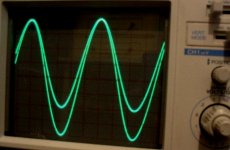
If you match them at 4 to 5 points from 1mA to 20mA you will have then had a single sine wave.
It's obvious that those pictured are not matched. If they were matched then your cro channel 1 and channel 2 is out of calibration at different volts/per division readings to measure low to high levels
Cheers George
It's obvious that those pictured are not matched. If they were matched then your cro channel 1 and channel 2 is out of calibration at different volts/per division readings to measure low to high levels
Cheers George
Hi,
just wondering if anyone has assembled a lightspeed p2p?
I've already put together a couple of 5v regs. using LM317s, and going to attempt to connect the ldrs to the rca jacks, etc... and make it as compact as possible.
just wondering if anyone has assembled a lightspeed p2p?
I've already put together a couple of 5v regs. using LM317s, and going to attempt to connect the ldrs to the rca jacks, etc... and make it as compact as possible.
going to attempt to connect the ldrs to the rca jacks, etc... and make it as compact as possible.
Tempting, but could be risky regarding higher heat from solder, which LDR doesnt like too much
Im all fore making it compact
Tho, theres a sensible limit to everything
Besides, its been stated that the LDRs are best "cast" into some compound fore equal heat allignment, which doesnt seem practical with the direct mounting on RCA
But maybe not impossible
But a small piece of not isolated solid core wire wont ruin the sound, at least not more than the RCA connectors, input selector, interconnect, etc
Dont know with the LDR att, but length of interconnects may matter
With normal "passives" its possible to tame speakers with a bit lively top, by using LONG interconnects
Maybe less with LDR
I would like to use a huge bank of small power supply caps
And use the smallest available print trafo
And cross my fingers that the small trafo doesnt burn on powerup
If you use that wire I gave you there wont be much heat involved as it heats up real fast as well as the legs of the LDRs. What I would do is get the wire and the soldering iron ready. Put some solder on the iron and then on heat the wire in the solder and give it about 2 seconds then move the wire and iron to the LDR leg and leave it only for another two to three seconds. No longer and when you remove the iron dont move that wire and blow on it. Should work fine but again I think these are the LDRs you already have soldered and it worries me that you will unsolder them then solder them again. I think its quite possible you will put to much heat on them. If you want to get a minimum amount of distance between RCA and LDR then just chop up that perf board you used to only be as big as necessary to hold your circuit then mount it right near the RCAs.
If you are using new LDRs then have at it, but beware to much heat. You could hold the LDR leg with pliers very right up against the LDR body so that you sink a lot of that heat to the pliers. This is not a catch all solution though and the pliers will still allow it to overheat but it might take another few seconds to happen.
Uriah
- Home
- Source & Line
- Analog Line Level
- Lightspeed Attenuator a new passive preamp