KP,
I'd have to say the buffered Lightspeed and only because I need to use the MF buffer with the normal Lightspeed. I do like the B1 and maybe it is just the caps, but it seems a little less "natural", a touch of softness to dynamics and slightly rolled off higher register compared to the Lightspeeds. Hope that helps.
Rick
Is it the version of #1363 and #1366 of page 55?
Wouldn't it be better to use the shunt version (e.g. with a 50k series resistor) when using a buffer because of better distortion values of the 32SR2?
Wouldn't it be better to use the shunt version (e.g. with a 50k series resistor) when using a buffer because of better distortion values of the 32SR2?
NP Lightspeed buffer
Hi Rick,
The parts for the NP lightspeed arrived.
Can you post a picture of your NP buffer to assist in my layout?
Thanks
kp93300
Hi Rick,
The parts for the NP lightspeed arrived.
Can you post a picture of your NP buffer to assist in my layout?
Thanks
kp93300
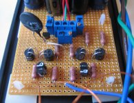
KP93300,
Here it is. The outside 1K resistors are input. I ran a single heavier signal ground wire to the rca's. The blue one at the center. I also connected the signal ground to the power ground through the thermistor. When I forgot to turn the Lightspeed on before the amp I got a terrible hum and this solved that.
I had a listen to the B1 last night and the Lightspeed has better detail and really brings the performers into focus. The B1 is nice but I'm stickiing with the LS for the time being. Hope that helps.
Rick
Attachments
Hi Rick,
Much appreciated for your picture and the helpful comments.
I hope to start the project today !
THanks
kp93300
Much appreciated for your picture and the helpful comments.
I hope to start the project today !
THanks
kp93300
Hi Rick ,
Can you provide the part number for the thermistor ?
Where did you source it from ?
Sorry to ask so many questions !
kp93300
Can you provide the part number for the thermistor ?
Where did you source it from ?
Sorry to ask so many questions !
kp93300
I think it is same as CL60. 10Ohm. One of NP's building blocks for everything. Mouser #527-CL60
@Georgehifi
Hi George
I enjoy very much listening with MKII as you named it.
But if I study the Silonex ANs (volumecontrol) the distortion of the shunt type is so much better than of the series/shunt version.
Is it the reason for MKII preference that we all love that tube-like sound simulation with the help of H2 distortions?
Tolu hi, with the different configurations that we tried over the many years the series/shunt (mkII) always came out on top, it had better bass impact, better dynamics and seemed to have greater extension top and bottom.
Whether this was due to the increase in 2HD I don't think so, I think more it had to do with the fact that the series/shunt (mkII) was a more constant input impedance and more constant output impedance, compared to the mkI 's wildly varying input and output impedance.
I did build one series resistor/shunt ldr (mkI) with a tube buffer ( a variation on a Tektronix Oscilloscope buffer) once that sounded good, this was with which we all agreed on was the best sounding buffer we ever heard (attached), but it was still behind the series/shunt mkII Lightspeed Attenuator without buffer, it was just better at driving low impedance <50k power amps.
Cheers George
Attachments

Hi George,
I don't understand what you mean with wildly varying input and output impedance of MK I.
If you put a 7k resistor as series resistor and vary the shunt resistance between 20 and 1000 Ohm you'll get an attenuation between -18 to -51dB and an input impedance between 7022 and 8000 Ohm with an output impedance between 20 Ohm (at -51dB) and 890 Ohm (-18dB).
In comparison to that you'll get with the MKII configuration at a constant input impedance of 7kOhm (if this is possible with the pot regulation) a varying output impedance between 20 and 780 Ohm (-18dB). Not that big difference I think!
Is it the magic of the optocouplers in comparison to a "simple" metal film resistor at the series side of the voltage divider?
Tolu, Build a series resistor and shunt LDR to ground that has a usable range, and you will see that in input and output impedances changes dramatically with different setting of the volume.
Where a series ldr and shunt ldr work opposite to each other in the mkII, the series ldr goes high while the shunt goes low and visa versa, this keeps the input and output impedances more constant than the fixed series and variable shunted resistance of the mkI.
The proof is in the listening, one is open dynamic and extended (mkII), where the other one is still smooth but dynamically challenged and compressed (mkI), unless it has a buffer, then that opens up a whole new can of worms.
Cheers George
Hi George, sorry to chip in here, if I'm talking rubbish then just ignore me😀
When you say varying impedance I'm a bit confused as you set the volume and leave it there so that it is constant.
Are you saying that the series resistor version works better at a certain impedance i.e. low or high volume but that the full LDR version works well at all volume levels?
If so then could the MK1 be better or equal to the MK2 at certain listening levels?
Cheers
Lee
George,
for further discussions I have attached a little pdf with the impedance progressions.
I believe in your experiences that MK II sounds better than MK I but if you take a look at the green sector it is hard to understand or to accept that impedance differences are the issue.
At an attenuation lower than -18dB MK II has advantages against MK I, but not at higher grades.
Attachments
Lee hi, read slowly and carefully the first two paragraphs in the post above yours.
BTW I'm all for using the mkI Lightspeed if a buffer has to be used after it, as then it behaves more like the mkII and it's much cheaper and far less time consuming to build also.
But I dislike buffers, we still have yet to find one that comes close to or equals a non buffered mkII Lightspeed feeding into a high, > 70kohm power amp input impedance.
As for the 7K series resistor this is not a given, it will have to be changed according to the system gain, otherwise you will have very little controllable range between min volume and max volume, minimum volume in some circumstances will be way too loud for some also.
Cheers George
georgehifi said:
As for the 7K series resistor this is not a given, it will have to be changed according to the system gain, otherwise you will have very little controllable range between min volume and max volume, minimum volume in some circumstances will be way too loud for some also.
Cheers George
As you can see in the sheet there is the same attenuation with MK I and MK II. It is an 1dB step attenuation. You can manage this with a DAC as I do at the moment.
The main problem I have is the high temperature drift of the optocouplers. The 0.7%/°C of the Silonex datasheet is nonsense. At the same room temperature a digitally controlled fixed current that feeds the LED let vary the resistance of the LDR +/- 10%! You have +/- 1 dB differences in dependance of device temperature, humidity, air pressure, UV ratios or what ever! This parts are extremely hard to control for a fixed LDR resistance!
All 4 LDR's in my production units all touch each other and then are all potted in extreme high temp wax, I think this is matbe why I do not get any drift, as well as the fact that the series ldr's will go the opposite to the shunt ldr's in drift, this may well help trackablity also.
Cheers George
Cheers George
Hi Thomas,
Do you use a current out or a voltage out DAC to power the LDRs?
For compensation of variances due to temperarture differences you can easily use the circiut SILONEX shows in the technical reference, Figure 14.
http://www1.silonex.com/audiohm/levelcontrol.html
This should work with voltage out DACs having the possibility to use a external voltage reference.
Best Regards
Arne
Hi Arne
it's a voltage out DAC, sorry.
Do you mean figure 15? The signal runs through a cheap opamp. That isn't the way I like to do!
I am thinking about a thermical reference platform in order to get constant voltage/resistance relations.
it's a voltage out DAC, sorry.
Do you mean figure 15? The signal runs through a cheap opamp. That isn't the way I like to do!
I am thinking about a thermical reference platform in order to get constant voltage/resistance relations.
Hi Thomas,
I mean Figure 14. You can use this circuit with a passive or buffered Lightspeed attenuator.
The control voltage runs through the opamp in this circuit, but not the signal. Use the +5comp as reference voltage for the DAC, if LDRs are directly driven by DAC.
Regards,
Arne
I mean Figure 14. You can use this circuit with a passive or buffered Lightspeed attenuator.
The control voltage runs through the opamp in this circuit, but not the signal. Use the +5comp as reference voltage for the DAC, if LDRs are directly driven by DAC.
Regards,
Arne
- Home
- Source & Line
- Analog Line Level
- Lightspeed Attenuator a new passive preamp