Anyone tried paralleling the LDRs
I noted that someone asked this kind of question before. It seems that if you paralleled some LDRs then you may not have to match them quite so much as they should more closely match the ideal specs.
Also if you had parallel LDRs then the low resistance would be lower and closer to zero volume (in the shunt position).
Anyone tried?
I think I am going to build a version as a volume control for my aikido preamp.
Thanks to georgehi for sharing.
Re: Anyone tried paralleling the LDRs
There is no reason why it shouldn't work. As a side effect tough the attenuator impedance will be halved, making it more difficult to drive.
I've just connected a Lightspeed clone (thanks Panelhead!!) to my Aikido and I'm quite impressed.
Sound is more dynamic and detailed.
Bass seems lowered but maybe it's just more controlled, surely more intelligible.
Cheers
andrea
beau2317 said:I noted that someone asked this kind of question before. It seems that if you paralleled some LDRs then you may not have to match them quite so much as they should more closely match the ideal specs.
Also if you had parallel LDRs then the low resistance would be lower and closer to zero volume (in the shunt position).
Anyone tried?
I think I am going to build a version as a volume control for my aikido preamp.
There is no reason why it shouldn't work. As a side effect tough the attenuator impedance will be halved, making it more difficult to drive.
I've just connected a Lightspeed clone (thanks Panelhead!!) to my Aikido and I'm quite impressed.
Sound is more dynamic and detailed.
Bass seems lowered but maybe it's just more controlled, surely more intelligible.
Cheers
andrea
felixx said:Hmmm...will see George's opinion.
Let's see, pro's and con's
More components
More conections
Harder to drive
Even lower source impedances needed
Different led voltage control needed
Nah, I'll stick to the hard way, and my motto, less is better, even if it is a PITA to do the matching.
Cheers George
TIME TO POST THIS AGAIN for those who havn't voted!
To all the 77,000 odd members that have been looking at this thread, we are all obviously interested in passive pre's of some description, be they pots, switched resistors, transformers or the Lightspeed.
I believe we need a PASSIVE PREAMP forum of our own, not to be stuck here in the solid state (yuk) forum. To get our own PASSIVE PREAMP forum you should vote here.
http://www.diyaudio.com/request/
Under the Passive Preamp Heading section that I have started with the first vote.
Please take the time to do this and get us out out limbo.
Cheers George
Just when I am ready to order some NSL-32SR2S over www.alliedelec.com they are out of stock. 
Well, they still have plenty of NSL-32SR3S so not sure if they get any NSL-32SR2S in near future.
Well, other than NSL-32SR3S are not sorted, any 'sonic' reason why we should stay away from it.
Well, they still have plenty of NSL-32SR3S so not sure if they get any NSL-32SR2S in near future.
Well, other than NSL-32SR3S are not sorted, any 'sonic' reason why we should stay away from it.
SamL said:Just when I am ready to order some NSL-32SR2S over www.alliedelec.com they are out of stock.
Well, they still have plenty of NSL-32SR3S so not sure if they get any NSL-32SR2S in near future.
Well, other than NSL-32SR3S are not sorted, any 'sonic' reason why we should stay away from it.
The NSL-32SR2S has an on resistance of 40ohm and off resistance of 5meg-ohm The NSL-32SR3S has an on of 60ohm and an off of 25meg-ohm!!! This type of spread (5x more) will make matching near impossible. Wait for the NSL-32SR2S to become available again. Sam I may have a source here in Australia for them, I'll let you know if it happens.
Cheers George
Can work, with volume pot impedance
I ordered all R3S by mistake. The maching was a little tough, but was not much worse than the 3 grades of R2S I just finished going though.
With the R3S you need to use a lower value log pot for control. If you are building one like a Lightspeed with two LDR's connected to each end of the pot a 25K log control should give about a 10K passive. A 50K pot will end up about 22K impedance "Lightspeed".
I just redid mine and installed G grade R2S in place of the H grade R3R. To get about the same impedance the pot value was changed from 50K to 125k. The ended up as about a 10K impedance control. Mine uses mono controls with only one LDR at each end of the pot. To get even a closer match of channel to chanel impedance, the pots were swapped around to get the closest possible matching between channels.
Matching these things is fairly time consuming. And there is a hysteresis effect, where the resistance is different if measuring after increasing the current or decreasing it.
This not a big issue in actual use, once a volume level is set is not changed very much to make temp drift an issue.
I am always thinking things sound better after changing, and matching up the diodes, installing new ones, then swapping the pots around to further match the impedances took a full 8 hours of steady work.
But it did seem to sound a little better with the R2S inplace of the R3S. Might entirely be in my head to justify spending a WHOLE evening from 2pm to 2am getting it right. But I think it is cleaner, punchier, and warmer. Course after spending that much time, one has to think it is better.
BTW, Andrea those you have are R3S also.
So I got to say; the R3 will work just fine, and maybe the R2 end up sounding a little better in use. Matching up is a PITA with both. The things have a giant tempco. Now using five currents levels correspond to pot all the way open-200 ohms, all the way closed- 125K, and 1.21, 49K, and 90.9K to get intermediate points. And still the incircuit measured impedance and tracking took a little adjusting.
But - the sound is sooo sublime. Made me rip the active board of the other unit to upgrade it to a straight Lightspeed passive.
George
Re: Can work, with volume pot impedance
Tried to tell you George way back, a properly implemented Lightspeed passive cannot be bettered, no matter how good the active stage is, whether solid state or tube, it is a compromise, compared to a passive Lightspeed.
The soul of the music is lost not to mention transparency if not used as designed, all that happens is the hifi sound comes back into it when active stages are introduced, squeezed out highlighted dynamics, instead of big effortless top to bottom dynamics with no squeezed out highlights.
Cheers George
Panelhead said:But - the sound is sooo sublime. Made me rip the active board of the other unit to upgrade it to a straight Lightspeed passive.
Tried to tell you George way back, a properly implemented Lightspeed passive cannot be bettered, no matter how good the active stage is, whether solid state or tube, it is a compromise, compared to a passive Lightspeed.
The soul of the music is lost not to mention transparency if not used as designed, all that happens is the hifi sound comes back into it when active stages are introduced, squeezed out highlighted dynamics, instead of big effortless top to bottom dynamics with no squeezed out highlights.
Cheers George
Yes, but what do we do when we have low impedance power amps? Doesn't this make the active buffer amp mandatory?
Regards
Regards
Harry3 said:Yes, but what do we do when we have low impedance power amps? Doesn't this make the active buffer amp mandatory?
Regards
Yes it does Harry, but knowing the difference for myself, there would be no question for me, it's that cut and dried, either to fix the impedence problem, if that is not possible, change amps.
Cheers George
Sanity Check on Design
Hello all,
First I would like to give a shout out to Georgehifi opening his designbook on the LDR attenuator. It is people like Georgehi and Sir Nelson Pass that allow lesser knowing hobbiest like myself to learn all things audio that I would have never have thought I would ever understand. Being and Engineer (not Electrical), it is human nature for me to get somewhat fanatical on new concepts (drives the wife batty) and this Lightspeed Attenuator is one of those new concepts I can't get off my mind...
Anyway, along with the praise, I do have a request. A sanity check on my LDR attenuator before I connect to my amp/speakers. The amp is a self-built UCD400 (100k Ohm input Impedance) and my self-refurbed Magnepan MGIIIa's. The source is a simple DVD player with a fancy DAC. Output is standard 2V.
I have purchased the NSL-32SR2S (10 of them - after waiting three weeks to arrive) and made a halfassed attempt to sort them...
First, the 5VDC supply is basically a 19VDC Laptop powersupply through an LM317 with a pot so I can dial in any voltage within 2VDC to 17VDC - so I have a nice clean 5.02VDC output to the Attenuator board.
Connecting the power to the Dual 100K pot as noted, I get a range of 5VDC to 4.95VDC (unloaded - unconnected to the attenuator board) with pot fully turned ClockWise, and the other side the exact opposite. Looks to be per design.
Next, I connected all the Grounds (power, signal in/out, LED side of LDR) together and connected the 5VDC power source to the 100K pot. The resistance range between each channel LDR signal input and output goes from 9.5K Ohms to 0.05K Ohms (turning dual pot fully counter clockwise is .05K Ohms). The other side works identically. I had to dial in the two 9.5K Ohm sides to match via the trimpot as they were slightly off by around 500 Ohm. Trimpot ground is left floating.
Everything seem in order?
BTW, why two trimpots? Trimming one channel down inversely affects the other channel...
Again, thanks for the help and the inspiration.
And I appologize if this was discussed earlier...
100 ohm current limiting resistors?
I hope you have installed 100 ohm current limiting resistors at each end of the pots. The LDR operate at around 2.5 volts. If you hit them with 5 volts and no series resistance the LED's will go very quickly.
I use mono controls instead of trimmers. So the resistors are 200 ohm, if stereo 100 ohm works well.
If you still measure a resistance as the pots are rotated, all is well.
George
I hope you have installed 100 ohm current limiting resistors at each end of the pots. The LDR operate at around 2.5 volts. If you hit them with 5 volts and no series resistance the LED's will go very quickly.
I use mono controls instead of trimmers. So the resistors are 200 ohm, if stereo 100 ohm works well.
If you still measure a resistance as the pots are rotated, all is well.
Each end of the Pot - are you talking of the 1K Trimpots? The initial schematic had a single 100 ohm resistor between the trimpot and + LED side of LDR. Is there supposed to be another 100 Ohm resistor between the 100K main pot and the Trimpot? I have only four 100 Ohm resistors and two 1K trimpots on board.
Do my resistances at the Signal Input/Output of the LDR look correct? They seem low and seem opposite to me (9.5K Ohm at full Clockwise position on Main 100K Dual Pot)
I know this is a shunt type design, just not very familiar with them...
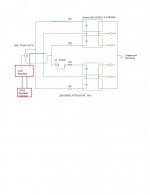
john65b said:Like this from previous post -
Just like that John, except use only one 1K trimpot on the loudest of the two channels, this is becomes a final calibration for channel equalizing (matching).
Glad to see you've built one for yourself, give use an appraisal on how it sounds to you, and don't forget to vote for the Passive Preamp forum.
http://www.diyaudio.com/request/
Cheers George
My version as volume control for Aikido
I built a variation on the theme, to suit my own needs. Basically I wanted a volume control for my 6SN7 Aikido preamp.
I had some different design goals:
-- I did not want the low input impedance of the Lightspeed design
-- On the other hand it does not have to drive cables, only the grid of a triode.
-- I wanted to use a high quality resistor as the series pass element, and use the LDR as the shunt element.
-- I had some gain to burn.
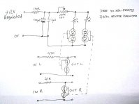
-- I had a 12V nicely regulated supply available.
With the setup I have, the LDRs range in resistance from about 70ohms to 12k (each). So note that at maximum volume the series pass is 47K with shunt of 24k, giving only about 1/3 of the available voltage. This is fine in my application.
Also the minimum volume setting still gives a nice quiet late night listening level. There is a mute switch on the preamp for zero volume.
The design I came up with is shown below, and it works very well, comfortably beating the Alps pot I was using before.
I have on order a relay switched attenuator, so I will be interested to compare that and the LDR. I may end up using the switched attenuator to control the LDRs. Why? The attenuator has remote control..
Note that this design will not work as a passive preamp as the output impedance is too high to drive cables, and you will be better off building the Lightspeed design (or the series/shunt Silonex application note design)
I built a variation on the theme, to suit my own needs. Basically I wanted a volume control for my 6SN7 Aikido preamp.
I had some different design goals:
-- I did not want the low input impedance of the Lightspeed design
-- On the other hand it does not have to drive cables, only the grid of a triode.
-- I wanted to use a high quality resistor as the series pass element, and use the LDR as the shunt element.
-- I had some gain to burn.
-- I had a 12V nicely regulated supply available.
With the setup I have, the LDRs range in resistance from about 70ohms to 12k (each). So note that at maximum volume the series pass is 47K with shunt of 24k, giving only about 1/3 of the available voltage. This is fine in my application.
Also the minimum volume setting still gives a nice quiet late night listening level. There is a mute switch on the preamp for zero volume.
The design I came up with is shown below, and it works very well, comfortably beating the Alps pot I was using before.
I have on order a relay switched attenuator, so I will be interested to compare that and the LDR. I may end up using the switched attenuator to control the LDRs. Why? The attenuator has remote control..
Note that this design will not work as a passive preamp as the output impedance is too high to drive cables, and you will be better off building the Lightspeed design (or the series/shunt Silonex application note design)
Attachments
Well I finally got around to checking the LS attenuator out - I had to try it on my "beater" amp (P to P Gainclone with Sony CD Player and Polk Audio speakers)
Anyway, the gain is too high - 1/4 turn was almost full LOUDNESS (this may have been covered elsewhere for Gainclone and Lightspeed Attenuator ) and the pot was reversed (fully CW was lowest volume)
Anyway, I was able to listen at moderate levels and I like it. Seems to best my Parasound PHP-850 Preamp. I need to do a few mods before I put it in a nice chassis and try it on my UCD...
I have a 250K single pot with power switch I may try to lower the gain.
john65b said:
Anyway, the gain is too high - 1/4 turn was almost full LOUDNESS (this may have been covered elsewhere for Gainclone and Lightspeed Attenuator ) and the pot was reversed (fully CW was lowest volume)
Anyway, I was able to listen at moderate levels and I like it. Seems to best my Parasound PHP-850 Preamp. I need to do a few mods before I put it in a nice chassis and try it on my UCD...
I have a 250K single pot with power switch I may try to lower the gain.
Remember it has to be 100k logarithmic if using my identical circuit, if it is a linear the volume comes on way too quick just as you described 1/4 turn too loud, with the logarithmic it is normal listening level at 1/2 then get really gets going from 2 o'clock onwards, just how it should be.
Cheers George
- Home
- Source & Line
- Analog Line Level
- Lightspeed Attenuator a new passive preamp