Here is an email I recieved from a customer who also has the EVA 2, this is what he had to say about the direct comparssion.
----- Original Message -----
From:
To:
Sent: Thursday, December 23, 2010 4:32 PM
Subject: Re: You've received a payment
George,
The lightspeed is great and is "light" years ahead of diyparadise's EVA II.
It is much quieter and linearity is perfect.
Regards, S
Cheers George
----- Original Message -----
From:
To:
Sent: Thursday, December 23, 2010 4:32 PM
Subject: Re: You've received a payment
George,
The lightspeed is great and is "light" years ahead of diyparadise's EVA II.
It is much quieter and linearity is perfect.
Regards, S
Cheers George
Mike
Why not just try it the way it is first? I have used down to 47k input impedance with no problem. A few people have experienced problems and if you are having an issue then just remove the lightspeed and do your work inside the amp.
There is an input resistor going from signal to ground inside your amp. Its the first thing the signal encounters unless there is a small 1k or so series resistor as well. So take that resistor going to ground and replace it with 100k.
Someone shoot me if I'm wrong.
Uriah
Uriah, you're not wrong.
The signal>ground resistor inside the amp is essentially parallel with the Lightspeed's shunt resistor, so increasing the amp's ground reference resistor will bring things closer to the shunt value.
Alternatively, you could replace the amps input resistor(s) completely by integrating the LS into the amp.
Alazira,
Thanks, that seems like a fairly easy mod. I think the toughest part will be working in the crowded chassis of the A3CR.
Thanks, that seems like a fairly easy mod. I think the toughest part will be working in the crowded chassis of the A3CR.
Here is an email I recieved from a customer who also has the EVA 2, this is what he had to say about the direct comparssion.
----- Original Message -----
George,
The lightspeed is great and is "light" years ahead of diyparadise's EVA II.
It is much quieter and linearity is perfect.
George,
That's interesting. If I put my ear within 3" of the tweeter I hear I hear a bit of a high pitched buzz, presumably digital noise or from the PSU, but it's not bothering me. I haven't noticed linearity issues. There is some conversation on the diyparadise forum from the designer implying that the Eva has circuitry to adjust the voltage between the channels to keep the LDRs balanced, English is not his first language, so it's not entirely clear.
I had a look inside the Eva II. It uses the same Silonex opticouplers as the Lightspeed. It does add a relay for switching (Fujitsu 46ND004-F1, gold over silver palladium contacts). That's the only difference in the signal path. It uses a digital pot (Microchip MCP4251) and a remote receiver chip (Microchip PIC16F882), which I suppose could generate some noise. The voltage regulator is is an ST L7805CV, which might also add some noise and I suppose the wall wart might add some too. Perhaps the regulator isn't as good as yours.
George, I am a minimalist like yourself which is why I want to move to a passive, but my system is a family friendly, multi-source, home entertainment centre. Surprisingly, my family rejects the idea of switching sources with cables 😱 and remote control of volume and mute is a given, switching optional.
I was building a transformer passive, but after reading this thread I abandoned that. I will use LDRs for volume control but I want a remote to control volume and mute. The Eva's three inputs are insufficient for my needs, but the rest is there and I can add inputs.
I acknowledge that even a single relay could compromise signal quality, but the effect should be negligible given all of the other elements in the total system signal path. Perhaps a regulator replacement and a better wall wart might improve things in the Eva.
The bigger issue with the Eva is the lack of volume, HF roll-off, and the operation of the remote. I will listening tomorrow to the Eva through a fellow DIYaudio member's DCB1 buffer, but I would rather change the impedance of my poweramp and avoid the buffer's active circuitry, no matter how minimal. I am intrigued that others are getting satisfactory volume, drive, and FR with moderate impedance poweramps and the Lightspeed.
If I can't resolve the issues with the Eva, then I will look for a replacement LDR/remote solution. There doesn't appear to be an affordable commercial option other than the Eva, so I might end up with a DIY solution (but hey that's why I am here). P&S Technologies offers a remote DIY LDR kit, but it's expensive and other than a positive review on TNT-audio there isn't much info available. I will also look at Paul Hynes remote.
Thanks to all for suffering through this long post and a special thanks to George for championing LDRs.
remote volume control for LDR's
I am no electronics expert, but there is a lot to be learned on several diy forums. So this is how I built my own DAC with volume control, since most of the music comes from CD or USB from the computer, and the DAC I built puts out sufficient voltage to drive my speakers very, very loud.
The DAC ( all DDDAC)has a USB to I2S coverter circuit, a SPDIF to I2S converter and a direct I2S input through a RJ45 receptacle (I2S iconnection cable is a cat5 FTP cable) Through a 3 position rotary switch I can select the I2S signal that comes directly from the Cd Transport, or the one from the USB converter board or the one from the SPDIF converter board.
The signal goes from the switch to several DAC boards, all using 12x TDA 1543 Dac chips in parallel.
The analog output goes through coupling capacitors to a LDR attenuator board (Uriahs kit) and from there to the RCA plugs connecting to the power amps ( two 7Watts Klimo Beltaine monos with 300B).
The volume is controlled with a motorized dual 100K Alps poti (regulating the Leds of the LDRs circuit and thus the volume ) through a remote control circuit from Dantimax. I am only using the motorized control feature, but it has two relays to be used as mute and power on.
So the DAC box does it all, acting as a switching passive preamp with remote volume control.
Since I wanted remote control for the volume, I could not use a stepped attenuator, so the LDR solution was perfect.
Sounds fantastic
Attachments
Michael from what I've been told the Eva II is just a single LDR and a resistor same as my older MK I model Lightspeed Attenuator, if so this is definately bettered by the MK II series and shunt ldr.
Also the HF noise you are at the speaker could be because they used an SMP wall wart, I use Linear ones, as I have seen the noise difference on the audio output on the scope it's more than double.
Cheers George
Also the HF noise you are at the speaker could be because they used an SMP wall wart, I use Linear ones, as I have seen the noise difference on the audio output on the scope it's more than double.
Cheers George
George,
Definitely 4 Silonex LDRs and a SMPS.
Cheers
And there's where your HF noise is comming from, a dirty switch mode power supply.
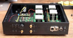
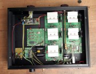
And from a high res photo of the guts I was sent by an anonymous sender, they don't use Silonex NSL32SR2S's, it's a far cheaper one so they can max out on profits, and to boot they have input and output mini relays in it, this is the exact reason for the Lightspeed Attenuator, "it's to get rid of all contacts between the source and poweramp" not add more contacts, no wonder it does not sound as good.
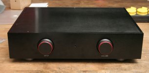
But it does look cute, with remote and digital readout, this will attract the naive customers.
Cheers George
Last edited:
And there's where your HF noise is comming from, a dirty switch mode power supply.
And from a high res photo of the guts I was sent by an anonymous sender, they don't use Silonex NSL32SR2S's, it's a far cheaper one so they can max out on profits, and to boot they have input and output mini relays in it, this is the exact reason for the Lightspeed Attenuator, "it's to get rid of all contacts between the source and poweramp" not add more contacts, no wonder it does not sound as good.
But it does look cute, with remote and digital readout, this will attract the naive customers.
It's pretty common for vendors to supply a SMPS wall wart standard as it lowers the entry cost, is good enough for many customers, and it allows the option of a future upgrade, either from a commercial or DIY source. The first place many of us upgrade is the PS. But I do understand that your unit has a superior, two stage supply.
I don't know about the quality of the LDRs. Mine are clearly Silonex. The model number is not marked on the LDRs, but they have "309" on it and appear identical to many pictures of assembled units I have seen (many of which are also 309s).
My unit has 3 input relays, but no output relay. As I said in post #3904, while I appreciate that some (including yourself) are absolute minimalists, I want remote control of volume at least and I need to switch more than one source. I can live with a single sealed, silver, relay in the signal path. The beauty of an LDR attenuator is that the remote functionality is outside of the signal path.
I don't think that I am "naive" because I trade a single point of sealed silver or gold contact for a significant increase in functionality. That's just a compromise. A true minimalist would solder the interconnects to the equipment "to get rid of all contacts between the source and poweramp." I notice that you provide your customers the convenience of RCA jacks, despite the sonic compromise. I would eliminate the jack before the switching relay.
Cheers
Sorry Mike didn't mean you were naive, but it will attract them.
As for the NLS32RS2S (selected) they have a batch letter R2C and the number of 208 on my last batch, and I've also noticed they have much thicker legs on both sides, than the NSL23RS2 that I have had which had the number 401C on them with thinner legs. I think the ones in the EVA 2 could be something else again from Silonex. As for the relays, there are 3 of them with 3 transistor drivers one each and which look to be DPDT double pole double throw, unless they used one for each input?
Cheers George
Cheers George
Last edited:
Silonex has changed their manufacturing. You will soon see ALL the LDRs having thinner resistor side legs. LED legs are the same.
309 has been on SR2 for a few years now, when purchased from Allied. I get other numbers on the side but that one shows up often. I bought 1000 LDRs this fall and they all had the thin legs and a 4 digit number on the side, all SR2. This last batch I bought over Christmas has the 309 again, well half of them do. Forget whats on the other half right now.
They put a 3 page announcement from Silonex on this last purchase (oddly it wasnt on the previous one) saying how they were changing manufacturing facilities and the leads would be a bit thinner we could all alter our through hole size apparently. Still sounds the same 🙂
Uriah
The last batch of NSL32SR2S I recieved I had to wait for from Silonex to be delivered 4 weeks ago still had the thicker legs.
Cheers George
Cheers George
Another Lightspeed review?
Hi everyone.
I ve been very interested in hearing a Lightspeed in my own system for a long time, and reading the rave reviews about it everywhere on the net fueled my enthusiasm even more.
I would like to thank Mr George who has been kind enough to share his ideas and design with the rest of the community. This in turn has given rise to countless permutations of the original, where the extra efforts have mostly been focused on the PSU and noise improvements.
A friend of mine who is knowledgeable in electronics decided a while back to build the latest version of the original Lightspeed. He finished it a few days ago, and after measurements and checking and rechecking and optimizing the PSU, we finally sat down yesterday for some critical listening. I would like to point out that we compared the unit against a pure resistive divider.
This might not be the right place to post these comments but I have to tell you that my initial impression was less than enthusiastic.
I would like to know if there are any others who have had similar experiences with this obviously very intriguing and wonderful design.
Here is what i heard:
Low frequencies sounded slightly cluttered and imprecise. I experienced an artificial roundness in the bass that was quite obvious after spinning many familiar discs.
Midrange was much warmer and slightly grainier compared to the resistive divider and once again percieved as artificial.
However, this did not seem to effect the soundstage in which the midrange frequencies were recreated -- strange.
I perceived highs as being rolled off and slightly congested. This inevitably lead to a perceived loss of detail in the music.
As previously mentioned, the soundstage was - astonishingly - completely intact compared to the purely resistive divider.
My friend measured the frequency response with and without the Lightspeed in the signal path and could not find any discrepancies.
Have you had any similar experiences? if not, what do you think the problem might be?
Thanks.
System parameters:
Amplifier input impedance: 1 Mega ohms
CD output impedance: 50 ohms
cheers
Strange, can I ask what were the specs of interconnects from cdp to Lightspeed and from Lightspeed to poweramp
1: Lengths?
2: Capacitance per foot?
3: What was the volume position on the Lightspeed for normal good level listening?
4: Does the CDP have an output dc offset blocking capacitor, and what size is it?
5: The pure resistive divider you used was just simple soldered in voltage divider at a set volume? consisting of a soldered series resistor and soldered shunt resistor, if so it would be interesting to know the values of the series and shunt resistor?
Cheers George
Last edited:
The interconnects used are 0.5 meters of Supra Interconnect EFF-1
from CD Player to the Lightspeed unit, and the same running from the Lightspeed unit to the amplifier.
# Resistance: 0.038 Ohms/m
# Capacitance: 77 pF/meter
# Nominal impedance: 75 Ohms @ 1 Mhz
# Propagation velocity: 0.66c
Supra Cables
CD Player is a Pioneer pd-95 modified a few years back with the zapfilter installed:
L C Audio Technology / ZAPfilter 2
Amplifier is lcaudio's Zapsolute class A 50W modified for 1 Mega ohms input ( I wanted to be able to connect it to valve preamps ).
The position of the volume control was mostly 8 to 9:30 since the power amp posesses high gain. I am not sure what resistance values this interval corresponds to, but my engineer-friend measured the total resistance of the lightspeed unit to be exactly 10 kohms.
The resistors used in the purely resistive divider was a 5600 ohms in series, with various values for the shunt resistor, all being under 1000 ohms. We simply connected the DC Coupled output of the CD Player to this very divider, and by changing the value of the several paralleled shunt resistors, we changed the volume setting. The argument behind this very awkward setup was proposed by my friend as to create the most neutral "volume control" that can be made to function as a reference.
Have you ever, under any circumstances experienced anything remotely similar? possibly due to some malfunction or a bad connection?
Thanks
Last edited:
All seems good to me, I am a big fan of the Zapfilter, did a lot of cdp mods using this, I did have quite a few rejects though with big dc offset problems (50-200mV), but they were all replaced sometimes twice and three times before I got reliable ones, you should check the dc offset regularly.
The only thing I have a question over is the amp is it a "class D (PWM) amplifier" as they seem to have stoped production of this, never been a big fan of them (PWM), and from what I've seen not successful at getting them to behave well with input impedances over 20kohm.
Cheers George
The only thing I have a question over is the amp is it a "class D (PWM) amplifier" as they seem to have stoped production of this, never been a big fan of them (PWM), and from what I've seen not successful at getting them to behave well with input impedances over 20kohm.
Cheers George
Yes Mr George. The Zapfilter was a revelation.
I was shocked at the level of improvement once it was installed in my already top-of-the-line CD Player many years back.
I have not experienced any problems with the DC offset. It measures (five minutes ago) 18 mV at the left output and 24mV at the right output.
The power amplifier is a Zapsoulte mk4 pure class A design, producing approximately 40 Watts of class A music while producing HUGE amounts of heat. The production of this underestimated jewel was sadly discontinued, as its magical creator, Mr Clausen of LC Audio decided soon after, that it was time to move on, and sold the company.
My amp was a factory-assembled unit ( with a slight modification installed at the factory that produced higher impedance ), and I have been using it since 2005 with great pleasure.
I totally agree with you on the class D amplifiers. Their sonic goal is far from what hi fidelity aims to achieve. I have listened to many ultra expensive, commmersially available class D designs, and many passionately-assembled diy efforts. None of them in mho managed to paint anything more than a gray, lifeless and congested picture of the musical event.
I know many people use them to power their subwoofers. I would not consider using them even for that!
Back to the Lightspeed, I honestly do not know what might be wrong with our assembly. Since I do not know anything about electronics, I have contacted my engineer-friend ( who built the kit, actually two ) and he informed me that he is going to recheck all the connections and voltages once more, and change the matched LDR's with the new matched ones bought last week.
It is however a puzzle to me, as the design is wonderfully straight forward, logical -- and according to everyone -- a sonic ace.
He told me that the PSU is built extactly according to your recommendations of the original Lightspeed:
1. Normal transformer-based, regulated battery eliminators 12 VDC out @ 300mA
2. Onboard chip regulator called LM7805
3. RC filtered 10 ohms 4700uF feeding the LDR's on the pcb via the dual volume control
4. LDR's mounted carefully on the pcb and soldered quickly at low heat.
Do you think there is anything we might have forgotten? any mistakes or mismatches?
thanks for your help
Last edited:
I have not experienced any problems with the DC offset. It measures (five minutes ago) 18 mV at the left output and 24mV at the right output.
Do you think there is anything we might have forgotten? any mistakes or mismatches?
thanks for your help
18mV & 24mV is quite high dvc offset for source equiptment. When working properly the Zapfilter are suppose to fluctuate between 1-5mV because they are dc servo'ed
As for the ldr's I have no more answers for you, I have seen the series ldr's cooked with high inputs from high levels of ac or dc esspecially when the output has been loaded down, one customer feed in 10v 1k sine wave while the output was close to shorted with a 100ohm load and this cooked the series ldr's so they only had a range of 50ohms to around 1k.
Cheers George
18mV & 24mV is quite high dvc offset for source equiptment. When working properly the Zapfilter are suppose to fluctuate between 1-5mV because they are dc servo'ed
I believe the possible reason as to why I have not had any problems with the DC on the output of CD Player is that it is probably further reduced by the voltage-dividing volume control. The power amplifier itself is DCservoed, thus compensating for any DCs present at the input.
As far as the Lightspeed goes I thank you for your help and as stated earlier, we will try to look at the rest of the circuit to find a possible explanation to this strange behavior.
Thank you
- Home
- Source & Line
- Analog Line Level
- Lightspeed Attenuator a new passive preamp