Don't doubt, just pot them together and keep away from fluctuating temperatures, and that will take doubt away. Even Silonex will tell you if you care to ask, they are temperature sensitive.
No need to pot the whole board/case, just the section with the LDR's, in the early days I used a Tick Tack container cut in half to sit over the LDR's to pour the potting mix into, when set just squeeze the container and it slip off.
Hint don't have the wax too hot, just when it melts so it's a little thick and not too runny.
Cheers George
Last edited:
This wax idea sounds like a nightmare to have in a hot amp George. I dread to think how it will all look in 5 years time. Surely there's a better way to pot the LDRs, like a small aluminium box, for example, filled with good old air, and insulated wires through small holes. Wouldn't that make more sense?
Even in wax it will not stop the drift inside a hot amp, and yes if hot enough it will soften the wax.
Cheers George
Cheers George
By a hot amp, I meant pre-amp in my case, with hot(ish) shunt regulators. I will pot mine in an aluminium Hammond case, for longevity.
Thanks for the heads-up about this vulnerability.
Thanks for the heads-up about this vulnerability.
By a hot amp, I meant pre-amp in my case, with hot(ish) shunt regulators. I will pot mine in an aluminium Hammond case, for longevity.
Thanks for the heads-up about this vulnerability.
You could use a Peltier Junction and external heatsink to cool your aluminium box to make it the first cryogenic preamp, and don't forget to insulate the outside surfaces to make it efficient . . .
Peltier Junctions | AllElectronics.com
Another way to reduce temperature sensitivity is to make an oven, just like a crystal oven, for the LDR's - a thermally insulated box with a heating element (big resistor) and temperature sensing element - control circuitry power the element to bring the temperature up to a desired value (warmer than ambient would ever be, maybe 95F for a stand-alone box, perhaps warmer for the inside of a power amplifier). Of course it would have to be calibrated warmed up, and when powered on may take a couple of minutes for the temperature to stabilize.
I could surround the ldrs with massive Conrad heatsinks, a cryogenic pad or two, with a computer controlled digital thermometer linked to a bevy of fans....
Or I could just bung it in an aluminium box and be done with it. 😉
Or I could just bung it in an aluminium box and be done with it. 😉
Me thinks it time for the moderators to step in, before this thread ends up in the gutter.
Cheers George
Cheers George
I have an Aikido preamp w/ ~500ohms output impedance and a classdaudio amp with ~47k input impedance. The Aikido is used to add some gain/tube love to my DACs and phono. Is there any way for the lightspeed to fit in the chain w/o adding something like the B1?
Me thinks it time for the moderators to step in, before this thread ends up in the gutter.
Cheers George
What do you think needs moderating?
Your system is compatible for a Lightspeed without buffer, you may enjoy it even more, as it will not have an transistor preamp thinness to it, as in a "hot" shot at you type transients. The transients the Lightspeed have has more body to them and sound more relaxed yet it will extend higher and lower than your tube pre.
If you feel the need for a tube buffer after it, this is the one that sounded best to me tube or transistor
Cheers George
If you feel the need for a tube buffer after it, this is the one that sounded best to me tube or transistor
Cheers George
Attachments
Your system is compatible for a Lightspeed without buffer, you may enjoy it even more, as it will not have an transistor preamp thinness to it, as in a "hot" shot at you type transients. The transients the Lightspeed have has more body to them and sound more relaxed yet it will extend higher and lower than your tube pre.
If you feel the need for a tube buffer after it, this is the one that sounded best to me tube or transistor
Cheers George
I'm assuming this is in response to my post. Thanks George.
post3632
George,
is that the schematic that was converted to mosFETs by one of our Members in Europe?
George,
is that the schematic that was converted to mosFETs by one of our Members in Europe?
Hi Andrew,
I posted a mosfet circuit, that is very similar in operation to the tube buffer, in post 1742 on page 175 if this helps.
Regards
paul
I posted a mosfet circuit, that is very similar in operation to the tube buffer, in post 1742 on page 175 if this helps.
Regards
paul
Last edited:
I've started work on my clone again. 🙂
Hopefully I'll have it up and running within a month or so. It's been collecting dust for too long.
Hopefully I'll have it up and running within a month or so. It's been collecting dust for too long.
post3632
George,
is that the schematic that was converted to mosFETs by one of our Members in Europe?
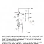
It is a buffer that Tektronics used in their top tier tube Occilloscope of yester year and called the "SLCF" Super Linear Cathode Follower, and yes it was reborn. For a tube buffer it has a nice low 100ohms output impedance, shame about the coupling cap thou.
Cheers George
Last edited:
rise and decay times
Hi all
I don't doubt that the lightspeed attenuator works well and like the concept but am struggling to understand how the optocouplers with a rise and decay time of 5 and 80ms respectively can follow an audio signal of 20kHz-can someone please help me with this...I'm but a mechanical engineer dabbling in electronics...
Thanks
Chris
the operator sets the "volume" by adjusting the current fed to the LEDs.
The LDRs adjust their resistance (slowly) to follow the light output of the LEDs.
After your time constant or seven have passed the LDRs have reached their final resistances.
These final resistances attenuate the Audio Signal that passes through the LDRs.
The Audio Signal does not pass through the LEDs.
If the design can hold the LEDs light output more constant then the resistances of the LDRs will be more constant. That's where regulation and capacitors come to our aid. To help fix the LED currents.
That rise and decay time - isn't that only relevant to the speed with which the volume control adjusts? In other words, isn't it the case that if you turn the volume up, that is the response time of the opto-coupled led to ldr, and not the response time of the ldr to the music signal?
- Home
- Source & Line
- Analog Line Level
- Lightspeed Attenuator a new passive preamp