Yes, the inability to comprehend Ohm's Law was the tipoff that this was software rather than a human. It's sophisticated, though; it can draw schematics with randomly-connected parts. Props to the developer, it's quite good.
See forum rule 1
Insulting, intimidating, bullying, harassing or other disrespectful or antisocial behavior.
SY, You should know better as a moderator, to refer to members as it, its, ie antisocial, and insulting,
Last edited:
My circuit performs extremely well with the NSL32SR2, it appears to me many here have sold or lost their soldering irons, pounce on words alone, but never the less are knowledgeable.... a conundrum.
Cheers / Chris
Cheers / Chris
OK, have it your way, it's not a good program.
You've been told repeatedly by experienced people that your designs don't make sense, the explanations are gibberish, your target (other than selling stuff to the gullible) is unclear, and that these are bad circuits, "designed" in complete defiance of basic electronics. Perhaps you expect people to fix your "designs" for free so that you can enjoy the sales unencumbered by the necessity of design costs, but expect that this will be pointed out and vigorusly so.
I am still unconvinced that there's a human back there- the resemblance to AI projects is uncanny.
Now I can't tell who is trying to make a fool out of whom.
But just through the questions and answers between Chris and I which I have quoted a while back, I feel that we should not even let the thread continue. Somebody might say something that accidentally turns into a big deal. It just seems to me that Chris as other intentions in similar nature of what has already been revealed.
You know, all this reminds me of the fights in the legislature here. The first representative that started this later admitted he started such practice just to get in the news and be seen.
Last edited:
Words have meanings, especially when arranged in meaningful sentences. Some of your words appear not to have their normal meanings. Some of your sentences may appear to a non-technical non-English speaker to be written in technical English, but are in reality neither. Computer programs can produce this sort of output. A sociologist who has studied 'electronics culture' and learnt some words (but not their meanings) might produce this. Anyone who understands both English and electronics would not write this stuff.Chris Daly said:pounce on words alone
hi BFNY
Yes there is another voltage source, that you are not considering. It is the inherent voltage given up by a single rail connected op amp...
with this schematic and assembled breadboard circuit you can simply measure current and voltage and resistance to confirm the larger schematics validity. ... what fun.
Cheers / Chris
Chris;
Since you have your breadboard out there, remove the op-amp, and connect the center wiper of the 50k R2 pot directly to pin 1 of U3 LM317 adj out.
Leave the LEDs connected as shown.
Tell me how that works controlling the LEDs.
I know that Google translation from Chinese to English make no sense most of the time. A friend tried to decipher a Chinese remark and showed it to me, I could not stop laughing.
Now I can't tell who is trying to make a fool out of whom.
It just seems to me that Chris as other intentions in similar nature of what has already been revealed.
You know, all this reminds me of the fights in the legislature here. The first representative that started this later admitted he started such practice just to get in the news and be seen.
you mean there could be something like this going on?
Columbia Cartoon Dumb Like a Fox (1941) - YouTube
That's a good one. How do you keep track of these videos? They really come in handy sometimes.
Last edited:
It's a random conglomeration of electronics terms, possibly pieced together from some random searches on keywords; that's how many of these bots function. Don't try to make sense of it.
The bot doesn't- it has no volition. The programmer may wish to recoup some of the cost by scamming. Or it could be a hoax.
I don't buy the bot theory, unless the OP is now bot-enhanced. His earlier posts appear genuine but a bit clueless, such as adding a 22K resistor around a Sallen-Key LP filter in a CD player in order to damage the frequency response. I reckon he is a circuit fiddler; maybe even another TV repairman!
I don't disagree with you often, but I have to in this case. I'm convinced it's a bot. Wouldn't be the first one we've had- there was once one pretending to be a female engineering student, star-something-or-other.
maybe I should start a fresh one?
Seconded...🙂
Then at least it will be coherent instead of getting lost in this inchoate thread.
look forward to your new thread...
Cheers Bob.
Done. New thread is here: http://www.diyaudio.com/forums/analog-line-level/209634-ldr-attenuators-better-balance-dc-bias.html#post2961580Seconded...🙂
(and previous post deleted to avoid duplication)
I wanted to unsubscribe from this thread, but interested in how this is going to end up.
DC can only have fixed bias, different balance can be needed at different gain settings. There is no fixed rule as to how to bias. I will probably join the other thread when this issue has some hope.
DC can only have fixed bias, different balance can be needed at different gain settings. There is no fixed rule as to how to bias. I will probably join the other thread when this issue has some hope.
Epilogue
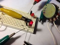
For grins, I took 10 minutes and built then tested the LED control schematic posted by Chris in post #150 here. Pics of test circuit below.
I used old diodes with about 0.5V typical drop in series with the LEDs, no sense wasting decent transistors here.
No surprises. A better subtitle would be
"how to abuse op-amps without really knowing".
First, no virtual ground. All nodes had voltages above 2V in all cases. Shocking, I know.
Second, all current goes through the pot wiper. Again, shocking. Or not.
What was interesting was how the circuit worked at mid wiper (in my case w/ actual 44 K ohm linear pot in mid position, 22k to each side). At mid position, current was minimum, and both LEDs were dimly lit.
At both ends of pot travel, one LED was bright, the other dark. I did not use a constant current control LM317 in front of the op-amp, to observe what would happen. At both ends of pot travel, full CW and CCW, with a +12V single ended supply, current through the wiper was about 60ma. In case anyone wonders, I actually opened the circuit at the pot wiper, and inserted my multimeter leads to make this current measurement.
This 60 ma is the TL072 op-amp current limit value for 2 sections (30ma x 2 as outputs are summed).
It's clear, the circuit grounds the + input, and drives the output to max voltage and current trying to achieve 0V on the - input. It's an expected outcome for a differential high gain amplifier. Oh well, so much for all the preceding rubbish about virtual grounds and so on.
But you already knew that.
Attachments
- Status
- Not open for further replies.
- Home
- Source & Line
- Analog Line Level
- Light Dependant Resistor Current Control