Low frequencies are long enough that facing forward is still close enough to half space radiation.I appreciate all the details. I thought we used near ground plane measurements with the assumption that we'd have no reflectios so was a very good way to achieve quasi-anechoic responses from woofers and subwoofers, even if the subwoofer was not actually embedded in the floor. 😀
We put the mic on the ground plane to assure there are no reflections, if the measurements are done out doors far from any reflective surfaces.
They don't.So I had thought that at low frequencies (wavelength >> diameter of driver) the wave fronts from each driver became planar.
Electrostatic loudspeakers typically exhibit a dipolar polar response, quite different from "a single flat wavefront".That is, if I added several woofers, I'd get the identical wavefront as if I had used a planar like an ESL. That is, a single flat wavefront.
If the ESL's rear radiation were enclosed, it's low frequency radiation would be that of a monopole with the same radiating surface.
The box baffle limits it's wavefront to hemispherical to the boundary wavelength. The individual point sources will exhibit constructive or destructive patterns depending on the off axis angle relative to vertical and horizontal spacing.So, reality with my 5 stacked subs is that I have 5 spherical wavefronts which will add and subtract in complex ways.
Yes, a theoretical rigid piston diaphragm 60" tall and 12" wide would have a different high frequency polar pattern than four 12" drivers in a vertical array.It's not the same as if I had a theoretical 5' tall and 1' wide driver in a box.
Is my last statement correct?
At low frequencies, it would have the same polar pattern as the 4x12" vertical array.
Yes, yes, I get that an ESL is a dipole, not really getting to what I don't understand. Question is in what ways are stacked woofers not a single radiating surface, and in what ways are they? It is that nuance I'm trying to understand.Electrostatic loudspeakers typically exhibit a dipolar polar response, quite different from "a single flat wavefront".
If the ESL's rear radiation were enclosed, it's low frequency radiation would be that of a monopole with the same radiating surface.
Yes, a theoretical rigid piston diaphragm 60" tall and 12" wide would have a different high frequency polar pattern than four 12" drivers in a vertical array.
At low frequencies, it would have the same polar pattern as the 4x12" vertical array.
Imagining multiple woofers stacked on a floor which is an infinite baffle, the polar radiation at say 10' away will appear as a rigid piston at low enough wave frequencies... so for this we can imagine a single piston but the reality is that we have multiple hemispherical wavefronts, so each is subject to potential interference from floor reflections at wavelengths far below the frequency at which they start to beam.
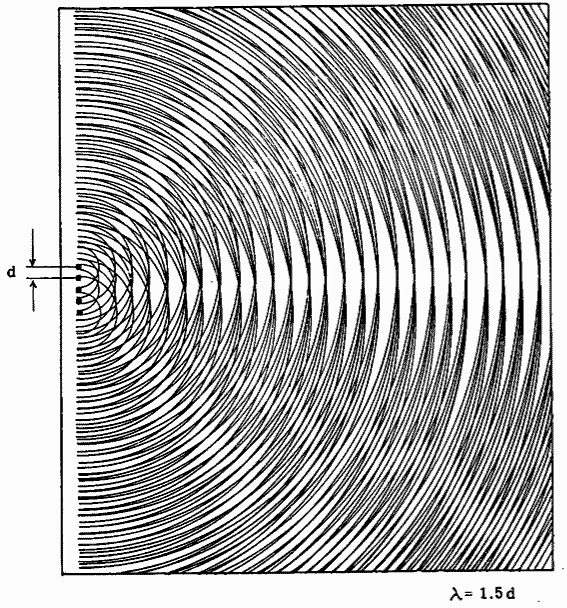
So going back to my question, we can approximate the single radiating piston in some ways, but not in others. The wavefronts are not magically planar, they just add up that way when you are far enough away. The reality is that when wavelength >> driver diameter we have multiple point sources. It's only at a distance and in approximation in some senses that we treat them as a single piston.
Last edited:
Both Tony’s & Mark’s multiple woofer subs, since they have even number of woofer’s, whynaren’tnthey push-push.
I like push-push, and have two different double 18" ported cabinet designs utilizing it. Really helps reduce cabinet vibration on asymmetrical bass transients.
But not for this project where I needed six smaller single sealed 18"s. I need to be able to put two each under LCR speakers, or three each under stereo.
Plus some other experiments...like vertical polars of a stack out on the driveway. If only I could figure out an easy way to stack all six !
Often so. But often not so, too. Depends on the consideration given to achieving line array goals with the stacks..Big towers that maximize visible woofers are “mine is bigger than yours” cosmetics.
Last edited by a moderator:
Imagining multiple woofers stacked on a floor which is an infinite baffle, the polar radiation at say 10' away will appear as a rigid piston at low enough wave frequencies... so for this we can imagine a single piston but the reality is that we have multiple hemispherical wavefronts, so each is subject to potential interference from floor reflections at wavelengths far below the frequency at which they start to beam.
To me, the question is when does a stack of radiators behave as a line source, rather than a collection of single radiators that have destructive interference (lobing) between them.
The two overarching guidelines that I know of are: the spacing between individual radiators c2c's determines how high in frequency they act as a line, and the length/height of the line determines how low in frequency they act as a line.
Necessary maximum c2c spacing for high end is generally quoted at 1/4 to 1/2 wavelength. Necessary total line length for low end at about a full wavelength.
I don't think the idea of point source fits into this 'line array rationale'. For me, a point source is a single omnidirectional source...the classic definition.
So in my mind, a beaming driver is the opposite of a point source.
I think in terms of multiple drivers each having their own radiation pattern vs frequency, based on driver size vs frequency. And again, the question becomes when do they act together as a line, and when do they act individually.
Hope that all made sense...
Hi, you could do some simple trigononetry, right triangle. Assume you are in front of the line, head at height of end of the array. Now, calculate distance from closest and furthest driver to your ear and they would sum constructively up to 1/4 wl difference. You'll find out the further you are the higher in frequency this happens. So, calculate at your listening distance to get some useful number.
OK, so lets ask when are they individual pistons and when are they a line source?I don't think the idea of point source fits into this 'line array rationale'. For me, a point source is a single omnidirectional source...the classic definition.
So in my mind, a beaming driver is the opposite of a point source.
I think in terms of multiple drivers each having their own radiation pattern vs frequency, based on driver size vs frequency. And again, the question becomes when do they act together as a line, and when do they act individually.
It sounds like the approximation of a line source happens because at long distances the interference patterns merge, giving us the behavior of a flat wavefront in a very practical sense, but the waveforms themselves haven't stopped being spherical, just that the effects end up combining.
Jim Griffin's line array white paper covers this and other aspects of line sources/arrays: http://www.audioroundtable.com/misc/nflawp.pdf
It sounds like the approximation of a line source happens because at long distances the interference patterns merge, giving us the behavior of a flat wavefront in a very practical sense, but the waveforms themselves haven't stopped being spherical, just that the effects end up combining.
I don't think so. I think it's when the drivers act as line source, ala classic Olson....that a non combing summation takes place due to tight (1/4 to 1/2 WL) c2c spacing.
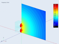
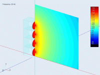
Some food for thought for @eriksquires on how the driver fields interact. These animated GIFs are BEM observation fields for 30cm piston driver(s), stacked and sitting on the floor (IB). The observation freq is indicated in the upper left of the pic.
Attachments
Going to PM you@Bmsluite Not a proposed design, but could be. 2x 6.5" and truncated dayton tweet
Just a example how I cheat make things easy for setting up your sim.
Basically all the work done, just to sim real quick from a old drawing I dug up.
I make a simple cad drawing, So I can arrange everything in the diffraction tool for drivers positions/baffle
Then know center to center distance to enter in X,Y all in a line so only Y
Tweeter is " listening position" so can start at 0, 0 for X,Y
In diffraction tool set drivers to those positions, with mic centered on each driver, export as full space vertical, horizontal off axis.
Then to get right phase, enter Y in crossover driver tap.
In crossover tap open 3 drivers, when your using diffraction tool you can also select " feed speaker"
Highlight the driver in crossover tap you want to " feed" too.
Saves time, hunting for your diffraction tool FRD exports, it just drops them right into the driver FRD
off course as you do each driver make sure you highlight the right driver in the crossover tap.
When I export in diffraction tool I give the name woofer 1 woofer 2 etc etc.
Making sure I didnt screw up the feed, since the FRD file names will a have a reference.
View attachment 1452325
Often so. But often not so, too. Depends on the consideration given to achieving line array goals with the stacks..
As always, a loudspeaker is a big set of compromises.
dave
Hi, you could do some simple trigononetry, right triangle. Assume you are in front of the line, head at height of end of the array. Now, calculate distance from closest and furthest driver to your ear and they would sum constructively up to 1/4 wl difference. You'll find out the further you are the higher in frequency this happens. So, calculate at your listening distance to get some useful number.
Taylor did it awhile back and don’t forget the Griffin paper.
The one picture story (nice animation ofthis Don):

In a rush, ca’t quickly find the paper, i have posted link often before.
dave
Last edited:
If only I could figure out an easy way to stack all six !
Hi Mark
How about using a big tripod with a lifting devise?
Then you could stak the cabinets from underneath, ie: Stack two cabs, fasten them together, lift up, put a third cab underneath, lower down, fasten to upper cabs, lift up, put the next cab underneath and on and on til all six cabs are stacked.
As a bonus the tripod can keep the the stack stable while measuring.
Regards, Steffen
Hi Steffen, I was half joking about wanting to stack all six. It wouldn't be very hard for though, I have a pair of Global Truss ST-132 crank stands from my foray into live sound that would make it pretty easy. Plus, the subs only weigh 60lbs..can almost get up em up a ladder safely. Oh, and they have smaller rubber feet and routed indentations on their tops for stacking, so pretty stable.
But yesterday testing out on the driveway, after i stacked three I got to 'what's the point of further stacking' unless i want to measure all around polars...which I don't. Results were too predictable vs modeling (like per DonVK's post) and summation SPL was spot on too. So I hit a who cares further point....
One thing I can say is...damn, even though I full well know it from many sub builds...sealed subs suck when it comes to the very bottom. Indoor measurement with room gain make them look ok, but outside they show their low end struggle.
EQ'ed flat, either indoors or out...they just ain't the same as vented...it's like you can hear the compression at higher drive levels. But I don't think it's something folks can hear / would know, until comparing directly with same driver vented. It simply takes two sealed subs to equal one vented, same driver.
- Home
- Loudspeakers
- Multi-Way
- Let's talk about the art of using Multiple Woofers


