Hi guys..
Just wanted to add my 2 cents worth.
The lid would be a challenge all by itself won't it. So get rid of it...or do it properly as well ...for instance make it extremely rigid and suck a vacuum under the lid as well...should kill any turbulences or other artefacts of "airborne pollution" such as dust but also airwaves.
Hope this helps.
Bas,
agreed. but i won't do it that way, having vacuum under the lid. One of my tonearm designs is an airborne linear tracker. Hard to keep the vacuum under the lid 🙂
agreed. but i won't do it that way, having vacuum under the lid. One of my tonearm designs is an airborne linear tracker. Hard to keep the vacuum under the lid 🙂
dice45 said:I am firmly decided that the TT sounds better with the lid removed completely from the plinth and i use a lightweight construction covered with transparent silk as dust cover if need one. I was able to convince many people to unmount the hinges from their TT lids and use the lid as dust cover the same way: remove/stash it away when spinning records.
Back in my hifi store days, when we were selling more higher end TTs than anyone else on the continent, this was our stand too. One of the reasons many of the used TTs around here just don't come with a cover. A cheap minmalist dust cover is a trashed record with a bulge at one part of the edge to lift it off (lighter held under record edge for a while does the trick.
dave
vacuum
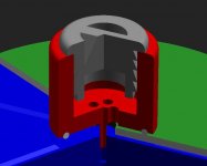
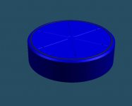
I've made a quick pic of how I think a simple vacuum system could work.
The idea is to use the winesaver valve and pump to provide the vacuum.
Air is sucked out on top through the hole in the disc and through the red part and the grey winesaver valve. The red part plus valve are left on when playing.
In one go you solve the centering problem. There is no spindle! You center the record before applying the vacuum. If you do this once and then draw a circle around the valve you can put it on right very easily from then on.
To make sure the valve is centered it has a small centering pin.
Peter
Attachments

Peter,
looks good! one minor objection: the label close to the center hole can be too rough to serve as parter surface for a vacuum seal. Maybe you increase the vacuum puck's diameter a bit?
Your idea to mark the pucks outline with a pencil is not bad at all! as far as practiccability is concerned but one has to spoil the beatiful label a bit 🙁 OTOH no centering pin adjustment is needed.
looks good! one minor objection: the label close to the center hole can be too rough to serve as parter surface for a vacuum seal. Maybe you increase the vacuum puck's diameter a bit?
Your idea to mark the pucks outline with a pencil is not bad at all!
as far as practiccability is concerned but one has to spoil the beatiful label a bit 🙁 OTOH no centering pin adjustment is needed.Maybe you increase the vacuum puck's diameter a bit?
Of course no problem🙂
true, but you don't have to draw a full circle. three points should be enough.one has to spoil the beatiful label
Peter
Peter,
the human eyes is very sensitive to parallelity of lines and concentricity of circles. You need a circle, i bet you need it. Today i mused how to draw your circle at the right place because with this circle you won't have to seek the excentricity maximum. You simply center circle to puck. Done in seconds.
Have to muse more about it. At the moment, i still need a measuring jig with a µscope on it. Maybe there is an easier way to find the right circle location?
Up to now, my thinking always was based on a mark, either close to the label edge or close to the center hole, showing where the ecentricity is and a center pin adjustable in excentricity.
Hi guis!
Yes, there are some folks still spinning vinyl here in Israel 🙂
I personally was waiting patiently for funds to be accumulated to puchase Teres stuff (platter+motor) as I came accross your exciting discussion. This made me think it is possible to build top notch DIY platter/base combo for more affordable price and certainly on more interestig way. Meantime the Ladegaard/Dennesen style air bearing tonearm with wooden framework is almoust ready and I am eager to test it on the really high end base/platter.
For the project matter: Why dont we combine air bearing ball with the platter partly floating in oil bath? I see here several important advatages:
1.Air bearing load is diminished by the platter bouyancy.
2. Somewhat springy nature of air bearig is effectively damped by oil.
3.The platter is well stabilised by its center of gravity placed below the bearing point and additionally by its submerged part bouyant force.
4.Air bearing is certainly superlative to any inverted bearing without lubrication. Why no lubrication? Because one could not rise the oil level in the bath UP TO bearing ball leaving platter outer rim at bearing point ABOVE the oil surface, and the belt has to lay in the same plane with the ball center point.
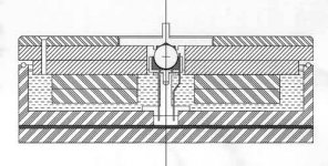
My proposal is: Redpoint- style sandwiched platter consist of upper vinyl/acryl(?) layer and two aluminium discs bolted together. Float part is made of polyurethane foam and glued under it. Pressured air is supplied through the small metal tube from below. The bearing cavity is vented to atmosphere with the other tube (yes, the closed chamber has to be vented, no matter what kind of bearing is used, just to get the same air pressure on two surfaces of the liquid). Several metal balls embedded in the pot rim used to prevent the platter from rough contact with the base.
Comments?
Yes, there are some folks still spinning vinyl here in Israel 🙂
I personally was waiting patiently for funds to be accumulated to puchase Teres stuff (platter+motor) as I came accross your exciting discussion. This made me think it is possible to build top notch DIY platter/base combo for more affordable price and certainly on more interestig way. Meantime the Ladegaard/Dennesen style air bearing tonearm with wooden framework is almoust ready and I am eager to test it on the really high end base/platter.
For the project matter: Why dont we combine air bearing ball with the platter partly floating in oil bath? I see here several important advatages:
1.Air bearing load is diminished by the platter bouyancy.
2. Somewhat springy nature of air bearig is effectively damped by oil.
3.The platter is well stabilised by its center of gravity placed below the bearing point and additionally by its submerged part bouyant force.
4.Air bearing is certainly superlative to any inverted bearing without lubrication. Why no lubrication? Because one could not rise the oil level in the bath UP TO bearing ball leaving platter outer rim at bearing point ABOVE the oil surface, and the belt has to lay in the same plane with the ball center point.
My proposal is: Redpoint- style sandwiched platter consist of upper vinyl/acryl(?) layer and two aluminium discs bolted together. Float part is made of polyurethane foam and glued under it. Pressured air is supplied through the small metal tube from below. The bearing cavity is vented to atmosphere with the other tube (yes, the closed chamber has to be vented, no matter what kind of bearing is used, just to get the same air pressure on two surfaces of the liquid). Several metal balls embedded in the pot rim used to prevent the platter from rough contact with the base.
Comments?
Attachments
livemusic,
looks like a very good idea. I see two challenges:
1)
to get the PU foam rings oilproof
2)
to get the PU foam rings symmetric and symmetrically/concentrically positioned enough that the float upforce does not make the platter tilt.
looks like a very good idea. I see two challenges:
1)
to get the PU foam rings oilproof
2)
to get the PU foam rings symmetric and symmetrically/concentrically positioned enough that the float upforce does not make the platter tilt.
Balls around the rim look good, that way if the rim touches, it doesn't go bezerk. Maybe not necessary- experimentation will show this. I feel better knowing we have this option.
As to the flotation, I think Dice is right- it will be tough to get adjusted right.
BUT this makes me realize that if we implement Bernhard's slightly hollow platter for vacuum, this will also make it much more bouyant-accomplishing the same as the foam.
Why not combine the air bearing and the oil damping!!
At first I didn't mention it because the pivot point of the air ball is quite a bit lower than a metal shaft with thrust bearing would be.
I thought: The platter would have to be hella thick to make this work.
Well.... our platter is now very thick! so why not?
Vacuum platter
Hi guys,
Congratulations on yr. TT project.
Regarding the vacuum platter:
Luxman had several TT models that used the same principle on an
aluminum platter.
Don't forget the risks involved though:
1/Too high a vacuum will destroy your precious record collection.
Vinyl being a relatively soft mold containing often a lot of ever so small porous cavities that will blow when suction is applied.
2/Apply a vacuum with a hard surface underneath yr record and any dust will be pressed into the vinyl record,permanently.
3/The same Luxman company sold their vacuum platter as an accessory for any turntable.It had a valve on the side where you connected an electric pump that sucked the air out.Once the air seal was tight you than manually closed the valve by a quarter turn and you disconnected the pump.
Bingo ! Another recordside destroyed.
For the record (no pun intended) I used to own both the Lux system and one by Thorens as well.
Neither did what they claimed yet did what they did not claim...
The best system I have ever used was one based on the slightly concave surface of the Goldmund range of TT.
It was made of metacrylate (which has an impedance close to vinyl) and was about 1 cm thick and could be fixed to the TT platter by pealing of the protective surface.
Since it was relatively lightweight it didn't block the platter against it's suspension as would the Lux contraption.
In combination with their record puck (which again was a clever device) you had the following benefits:
-the mass of the vinyl record was improved due to the tight coupling with the platter .
-due to this any spurious vibration energy created by stylus drag was sunk into the mass and not reflected back into the stylus.
-you actually had less stylus drag due to the better coupling.
-the record puck was also designed to absorb as much energy as possible from the spindle. (lots of TT's had their spindle as an integral part of the bearing assembly.NOT a good idea.
I and no doubt others can explain the academic thinking behind all this and if you all twist my arm long enough I just might.
Now if you think all this couldn't be heard.Think again!
http://www.retroaudio.ru/luxman/turntables/PD-310.shtml
Oh,and forgive me for saying so.
-The ball bearing in the latest drawings is NOT what is considered good engineering.Its contact area is way too great,causing friction is the last thing you want.
-Using a lid isn't either.
-Applying an airbearing here isn't either. (I can explain all this)
There I said it.
Bernhard,
Sorry couldn't restrain myself any longer.Deep sigh.
If I get the green light from you I will share my ideas with you all,be forewarned though it's got alot to do with mechanical impedances,mechanical diode principles and so on.
I spent 3 or so hours last night carefully reading all those threads regarding this post and went to bed exhausted and with a nagging feeling I had to share my experiences and knowledge.
If you don't mind I can send you an e-mail with an explanation of how I feel we can go about this in order to finalise this project.
Havoc,
I suppose you're not unfamiliar with this since I kind of suspect you read the French press a la L'Audiophile etc. too ?
To all who have contributed to this honourable project so far:
I don't want to hurt anybody's feelings.This is by far the most interesting and daunting project I've seen on any public forum, so please don't let these mean little comments of mine mislead you.
They are written with passion to help our community...
So now you can all shoot me.
I digress...
Keep up the good work,
Bring it On!!
I can't see any reason that peoples feelings would be hurt by someone contributing useful information. At this point, I think we have brought up some interesting approaches, now we need input by someone that can contribute on another level.
Please post your comments for us all and for others that might read this in the future. (even if it's pretty long!!)
The only incorrect thing to do would be to privetely discuss this this behind the scenes. This would indeed lead to hurt feelings , and conspiricy theories!!! No green light required. You do not need permission to post, and that is not how this discussion group works!!
Mark
Bernhard:
1. PU foam has closed cells. Dense PU foam (above 6 pcf) water absorption is negligible. It is also more rigid and has good resistance to lubricating oil (material handbook). So IMHO oil proofing is no issue.
2. Form stability/concentricity may cause a problem. I think dense PU foam sheet material about 15 mm should be used. Three layers of it form 45 mm thick float, with the air chambers in the middle layer. The main challenge could be to cut out the float discs precisely (kind a sharp tool combined with the rotating table?). Then the float can be attached to aluminum platter, first with some kind of temporary glue, to allow adjustment while the whole assembly rotated, making the marks with a pencil, then final glueing.
Mark:
Buoyancy gain is pretty small with the air chambers: submerged volume stays the same, actually additional buoyant force is equal to the removed material weight – for 6 chambers of 6 cm diameter it is about 25 gram for PU float. BUT, if more dense and rigid material is used for the float (acrylic?), a lot of connected chambers may be drilled in it and the float weight could be reduced dramatically.
Some additional points:
The air bearing may be not an easy task. Bigger diameter ball has to be used to reduce the air pressure. Here are some calculations. Assume 5 cm diameter ball is used; two layers of 1 inch aluminum (to keep the platter CG under the pivot point) and top layer of 1 cm acrylic for the platter, 3 layers of 1.5 cm PU foam for the float. Then the total weight is 10.3 kg, buoyant force is 3.2 kg and the minimum required air pressure is 5.2 psi.
First, the big ball may be not easy to find (could be good quality snooker ball?). The smaller ball requires more air pressure - 21 psi for 2.5 cm ball, for instance. Doubt aquarium pump would help, even for 5 psi. Any thoughts about air source?
Second, I really hope the epoxy bearing bed may be formed with the same ball. Otherwise it could be a nightmare to get two balls with 0.1 mm diameter increment while the air gap is taken into account.
Thank you for comments.
Michael
Sorry fdegrove, I do not read mentioned press, none of it at all. The reason I kept myself outside it all is that it is getting further and further away from my opinions on the matter.
Until some time ago, it was about getting a basic good to excellent quality TT on the map, better than anything you could buy for the same money. But when the discussions about the vacuum and the motor got in it I got out of it (well, sort of). I like this for the sake of the project, as it is something that can be tackled by many with results to match.
So at the moment my ways are diverging from the rest of the pack, and I'm studying my options. I'm also slowly getting in touch with some old contacts for having access to prototyping means and trying to get some materials together. This together with other obligations mean it is going in slow-motion at the moment.
naysaying complaint
fdegrove,
with your post you questioned practically everything contributed here by the other members. And your last paragraph showed clearly you are aware of possible effects. Then, why the heck do you post it? Why not simply post your ideas in a positve and constructive way and have them discussed?
Then,
If you manage to mentally penetrate within 3 hours what was written here, i am impressed, i would not be able and i am quite deep into the topic. Sometimes it takes me >30min to grasp what is technically intended (and at the moment i have to wrestle with understanding what the folks in the digital board are writing, i am not what you would call a complete digital dummy, but i am drowning in it)
Now i tell you why i am upset. I am moderator here too (some have accused me being moderate), i want the ideas flowing and growing and i want a positive spirit around here. I want everybody have fun and be happy with his TT design and with the inspirations he decided to pick up for it. I am definitely not moderate .. with any kind of naysaying and i am quite paranoid in this respect. I sense your post as such. 😡
In creativity workshops i have observed many cases where naysaying, telling that a thing cannot work and why in elaborate scientific detail has made participants .. get introverted and not tell anyone any more of their ideas or
  ..get mad. In any case: no further ideas.
In workshops i moderate (i happen to consider this thread as such) i do not let such things happen without taking means against it.
😡.. No naysaying! Instead, tell what you want to technically achieve and how! And give constructive and specific advice on specific QQ! And share your ideas with us, noone is biting, atleast not biting as 1st.
For the record, i do not consider it as naysaying if physical or technical laws commonly acknowledged as valid are in direct conflict with a design detail. But even then one can try to figure out together an in a constructive manner what to change in order to make the thing work without comprimising other techical goals alltoomuch.
fdegrove,
with your post you questioned practically everything contributed here by the other members. And your last paragraph showed clearly you are aware of possible effects. Then, why the heck do you post it? Why not simply post your ideas in a positve and constructive way and have them discussed?
Then,
If you manage to mentally penetrate within 3 hours what was written here, i am impressed, i would not be able and i am quite deep into the topic. Sometimes it takes me >30min to grasp what is technically intended (and at the moment i have to wrestle with understanding what the folks in the digital board are writing, i am not what you would call a complete digital dummy, but i am drowning in it)
Now i tell you why i am upset. I am moderator here too (some have accused me being moderate), i want the ideas flowing and growing and i want a positive spirit around here. I want everybody have fun and be happy with his TT design and with the inspirations he decided to pick up for it. I am definitely not moderate
.. with any kind of naysaying and i am quite paranoid in this respect. I sense your post as such. 😡In creativity workshops i have observed many cases where naysaying, telling that a thing cannot work and why in elaborate scientific detail has made participants
.. get introverted and not tell anyone any more of their ideas or ..get mad. In any case: no further ideas. In workshops i moderate (i happen to consider this thread as such) i do not let such things happen without taking means against it.
😡.. No naysaying! Instead, tell what you want to technically achieve and how! And give constructive and specific advice on specific QQ! And share your ideas with us, noone is biting, atleast not biting as 1st.
For the record, i do not consider it as naysaying if physical or technical laws commonly acknowledged as valid are in direct conflict with a design detail. But even then one can try to figure out together an in a constructive manner what to change in order to make the thing work without comprimising other techical goals alltoomuch.
TT
Bernhard and all contributing folks,
Take it easy please.
Read through it again and take all the time you need.
I phrased it very thoughtfully and asked specifically to you ,the moderator,if I should continue explaining my reasoning behind it all or not.
After reading you and realising last night already where all this is leading to I feel less inclined to do so.
Moreover reading some other people's posts on this topic I can only say I'm not the only one.
After all,if one is not allowed to question things I don't see any point in going on with it.
So I guess I got the red light on this one.Not my loss I think.
Rgds,
Mark,
Here is a copy of the e-mail I sent to Bernhard :
Hello Bernard,
Hopefully all is well at your end.
I have no idea if you looked into my last post in the TT thread but here is a quick overview of what I suggest we should do.
You've actually suggested some of it yourself but not everyone has stuck with it so here goes :
1/Divide the project in several subcategories:e.g. bearing,platter,motor+belt and so on...You catch my drift.
2/Someway to coordinate all this.
3/Decide exactly what kind of TT we want to design.The very best we can do or something more cut to a certain price range ?
Personally I prefer the first option with the eventual possibility to cut corners later on.
4/It would be very useful if we asked the contributing people in what way they feel they could best contribute to the project,e.g. some could do the CAD design,other could do some sourcing and so on.
5/Does the forum allow for say person to person threading between a defined number of participants?I realize it goes against the general concept of a forum but for the sake of advancing the project it would be a luxurious environment for a certain amount time.Like going into chat mode for example?
I realize you put already an enormous amount of energy into this and add to that the fact that I consider you one of the most knowledgeable contributors to the forum so I put this in your lap.
Also someone already suggested I should go ahead with it and go public with all this,still I prefer to take this bend for clarity's sake.
Best rgds,
Frank
Havoc,
Guess you felt it coming too.
Rgds,
matter-of-fact talk
fdegrove,
the ball bearing you complain about is an air bearing. big contact surface is desired, no contact or friction is happening due to the air film.
You say, have tried out the vacuum on an alu platter, i know this Luxman beast. I agree, it is a danger for the records. It has an almost binary vacuum.
But as you have read the whole thread, you certainly have observed i pointed out that vacuum must be partial and can made partial with the cavity system i suggested and which to my surprise and pleasure was adopted by others without further negotiation 🙂
I have to do some minor naysaying here myself, the wine vacuum pump contributed by Peterr has no vacuum limiting valve, this has to be added or the pump has to be used with care.
As i hide/distribute about 1l of space inside my platter, the wine pump would take ages for evacuating, so i did not consider it for my project.
My idea was to use a maximum of 200 mbar negative pressure, just what a vacuum cleaner is able to deliver.
I had two ideas how to provide the vacuum myself and a butchered vacuum cleaner motor was one of them (quick but noisy). The other one was a diaphragm suction pump as used for evacuating packaged food meant to be deep-freezed.
Slow and less noisy.
I wonder you do not mention the cheap Transrotor (or was it Thorens?) system with a sheet metal with vulcanized rubber surface, sucking thu the centerhole and the vacuum was kept by a compressible expansion bellows which then would suck by trying to expand again. A fellow student owned this, it never destroyed one record.
BTW, i own that Goldmund mat. It works on most records provided the clamp is not tightened binarily but moderately. But on 10% of my records i've got no chance to pull them flat and on some my SME V is in deep (or should i say 🙂 high) trouble as the clearance between record adge and arm wand is not sufficient for warped records on the VTA i prefer.
Moreover, on tonearms without azimuth adjustments, it is sheer luck that azimuth fits to the slope the Goldmund mat forces the record into; majority of the expensive MC cartridges is fairly horizontal nowadays as far as azimuth is concerned. I tell yo what i do once i have my new tonearm working: i have my buddy turn the hollow conus surface off the Goldmund mat.
I have got feedback from folks having build such a partial vacuum system i suggest (but did not have the chance to try out myself so far): they rave about it, all of them.
I have to confess: i once firmly believed in vibration guiding towards outside the platter or even TT plinth, i collected all possible statements referring to that. But then i studied signal engineering and my nose was force-rubbed into physics ... i abandoned one voodoo concept after the other.
For instance, you want them durned vibrations out and away, right? 3 theories out of 4 claimed the specific travel velocity of the vibrations has to increase from material to material from slow to fast. Reflection of glue layers was heavily discussed as glue has low travel velocity.
Albert Einstein would have two objections:
1st,
calculate the 20kHz wavelength at 1500m/sec and above, then consider layer thickness and its possible influence like observed in optical lambdy/4 filter coatings. Glue layer does not matter, period.
2nd,
the only mechanism keeping a portion of the vibrations, a spatial angle to be specific, from transitioning a material/material interface is total reflection and this is only working from slow to fast travel velocity, never inverse!
So material sequence has to be from fast to slow travel velocity, as then only the vibrations from within the spatial total reflection angle can wander back, whereas the vibrations from outside face total reflection and cannot wander back to the source (which we want to achieve).
The only material sequence achieving this starts at vinyl and goes down over PTFE to PE and then to putty (not yet hardened), to water, to honey, to air .... does not look as if those materials have the geometrical stability we desire.
End of example.
Mechanical diodes? I am not sure such exists. I have made lots of experiments with spikes and different trustplates. But i could not find their orientation or shape had any influence. Their material however had influence on sonics. ..And their actual location had!! With spikes i found out is that a 1st priority path is needed, one steel spike and two POM balls e.g. And it influenced sonics considerably if the spikes were positioned at vibration bellies, not at vibration nodes. Belly locations were clearly better (i spotted them with an old MM cartridge and an oscilloscope).
No Q, if the device sounds better if it can get rid of vibrations, i help it. For that, the ground must be a good vibration sink and the spike(s) located at a belly and preferably one spike only and two tiny pieces of plastic, not rubber, defining location and orientation in space and not allowing mechanical amplitude. Try it out with a speaker! Or a TT!
Later i developed a theory to help me to understand what i observed. Solid bodies are like jelly pudding or like supersoft silicone rubber, they shiver all the time from 3D vibrations ans oscillations. µscopically, of course. Just that the different "rubber" materials have differnent oscillation travel impedance and velocity, a different Youngs modulus of elasticity, limit of elasticity, Q factor and so on. But they shiver like jelly pudding all the time.
If the solid is wanted to swing, suportiis at nodes, if unwanted vibration energy is to be subtracted or led away, support the bellies.
To my surprise, i got backup from my physic professor as well as from the measurnig laboratory guys.
They all were ROTFLTAO on mechanical diodes but nodding to that fact that support point location can make a world of a difference.
From them on, i used bearing balls as spikes and o-rings to keep them from rolling away (it is not so important of the tip is sharp or if the ball is round, it does the same job: supporting at the right location without being able to insert any torque). And i marked ball location if i had found a neat sounding one. Before i forget it, bearing balls do not damage surfaces as spikes do.
Air bearing,
point is for me: i do not sacrifice the benefits of an airbearing just because there is no mechanical diode theory application possible (a theory i tried to prove and failed).
Instead i search and find a theory adjusted to the real life situation, see above.
Why do i use air bearings? because they run smoother than anything, no mechanical noise, and because they are stiff ! stiff ! stiff ! and not rubber-like gooey as a conventional shaft and bushing bearing trying to keep the huge platter in place and shivering from fear all the time while doing so.
And the air bearing is applying considerable damping to the jelly-pudding-like oscillating platter's bottom surface. Another benefit IMO.
And why do manufacurers of precision roundtables, of mirror milling machines do choose airbearings? For exactly the same reasons, if an airbearing supports planar milling of 60 Nanometer flatness, it will do for a TT.
So we are back in the design department. We design a TT. Anyone here of us is his own chief designer and we share concepts.
So far, i have seen many valid concepts, and all go right to the point. They set priorities. They are on level 5 . Spikes and mechanical diodes are on level 2. Periphery. Tweaking department.
Wire directionality. Sorry i say it that blunt, cannot help 🙂
--------------------
Have to re-post the seven levels of audio enlightenment:
fdegrove,
the ball bearing you complain about is an air bearing. big contact surface is desired, no contact or friction is happening due to the air film.
You say, have tried out the vacuum on an alu platter, i know this Luxman beast. I agree, it is a danger for the records. It has an almost binary vacuum.
But as you have read the whole thread, you certainly have observed i pointed out that vacuum must be partial and can made partial with the cavity system i suggested and which to my surprise and pleasure was adopted by others without further negotiation 🙂
I have to do some minor naysaying here myself, the wine vacuum pump contributed by Peterr has no vacuum limiting valve, this has to be added or the pump has to be used with care.
As i hide/distribute about 1l of space inside my platter, the wine pump would take ages for evacuating, so i did not consider it for my project.
My idea was to use a maximum of 200 mbar negative pressure, just what a vacuum cleaner is able to deliver.
I had two ideas how to provide the vacuum myself and a butchered vacuum cleaner motor was one of them (quick but noisy). The other one was a diaphragm suction pump as used for evacuating packaged food meant to be deep-freezed.
Slow and less noisy.
I wonder you do not mention the cheap Transrotor (or was it Thorens?) system with a sheet metal with vulcanized rubber surface, sucking thu the centerhole and the vacuum was kept by a compressible expansion bellows which then would suck by trying to expand again. A fellow student owned this, it never destroyed one record.
BTW, i own that Goldmund mat. It works on most records provided the clamp is not tightened binarily but moderately. But on 10% of my records i've got no chance to pull them flat and on some my SME V is in deep (or should i say 🙂 high) trouble as the clearance between record adge and arm wand is not sufficient for warped records on the VTA i prefer.
Moreover, on tonearms without azimuth adjustments, it is sheer luck that azimuth fits to the slope the Goldmund mat forces the record into; majority of the expensive MC cartridges is fairly horizontal nowadays as far as azimuth is concerned. I tell yo what i do once i have my new tonearm working: i have my buddy turn the hollow conus surface off the Goldmund mat.
I have got feedback from folks having build such a partial vacuum system i suggest (but did not have the chance to try out myself so far): they rave about it, all of them.
I have to confess: i once firmly believed in vibration guiding towards outside the platter or even TT plinth, i collected all possible statements referring to that. But then i studied signal engineering and my nose was force-rubbed into physics ... i abandoned one voodoo concept after the other.
For instance, you want them durned vibrations out and away, right? 3 theories out of 4 claimed the specific travel velocity of the vibrations has to increase from material to material from slow to fast. Reflection of glue layers was heavily discussed as glue has low travel velocity.
Albert Einstein would have two objections:
1st,
calculate the 20kHz wavelength at 1500m/sec and above, then consider layer thickness and its possible influence like observed in optical lambdy/4 filter coatings. Glue layer does not matter, period.
2nd,
the only mechanism keeping a portion of the vibrations, a spatial angle to be specific, from transitioning a material/material interface is total reflection and this is only working from slow to fast travel velocity, never inverse!
So material sequence has to be from fast to slow travel velocity, as then only the vibrations from within the spatial total reflection angle can wander back, whereas the vibrations from outside face total reflection and cannot wander back to the source (which we want to achieve).
The only material sequence achieving this starts at vinyl and goes down over PTFE to PE and then to putty (not yet hardened), to water, to honey, to air ....
does not look as if those materials have the geometrical stability we desire.End of example.
Mechanical diodes? I am not sure such exists. I have made lots of experiments with spikes and different trustplates. But i could not find their orientation or shape had any influence. Their material however had influence on sonics.
..And their actual location had!! With spikes i found out is that a 1st priority path is needed, one steel spike and two POM balls e.g. And it influenced sonics considerably if the spikes were positioned at vibration bellies, not at vibration nodes. Belly locations were clearly better (i spotted them with an old MM cartridge and an oscilloscope).No Q, if the device sounds better if it can get rid of vibrations, i help it. For that, the ground must be a good vibration sink and the spike(s) located at a belly and preferably one spike only and two tiny pieces of plastic, not rubber, defining location and orientation in space and not allowing mechanical amplitude. Try it out with a speaker! Or a TT!
Later i developed a theory to help me to understand what i observed. Solid bodies are like jelly pudding or like supersoft silicone rubber, they shiver all the time from 3D vibrations ans oscillations. µscopically, of course. Just that the different "rubber" materials have differnent oscillation travel impedance and velocity, a different Youngs modulus of elasticity, limit of elasticity, Q factor and so on. But they shiver like jelly pudding all the time.
If the solid is wanted to swing, suportiis at nodes, if unwanted vibration energy is to be subtracted or led away, support the bellies.
To my surprise, i got backup from my physic professor as well as from the measurnig laboratory guys.
They all were ROTFLTAO on mechanical diodes but nodding to that fact that support point location can make a world of a difference.
From them on, i used bearing balls as spikes and o-rings to keep them from rolling away (it is not so important of the tip is sharp or if the ball is round, it does the same job: supporting at the right location without being able to insert any torque). And i marked ball location if i had found a neat sounding one. Before i forget it, bearing balls do not damage surfaces as spikes do.
Air bearing,
point is for me: i do not sacrifice the benefits of an airbearing just because there is no mechanical diode theory application possible (a theory i tried to prove and failed).
Instead i search and find a theory adjusted to the real life situation, see above.
Why do i use air bearings? because they run smoother than anything, no mechanical noise, and because they are stiff ! stiff ! stiff ! and not rubber-like gooey as a conventional shaft and bushing bearing trying to keep the huge platter in place and shivering from fear all the time while doing so.
And the air bearing is applying considerable damping to the jelly-pudding-like oscillating platter's bottom surface. Another benefit IMO.
And why do manufacurers of precision roundtables, of mirror milling machines do choose airbearings? For exactly the same reasons, if an airbearing supports planar milling of 60 Nanometer flatness, it will do for a TT.
So we are back in the design department. We design a TT. Anyone here of us is his own chief designer and we share concepts.
So far, i have seen many valid concepts, and all go right to the point. They set priorities. They are on level 5 . Spikes and mechanical diodes are on level 2. Periphery. Tweaking department.
Wire directionality. Sorry i say it that blunt, cannot help 🙂
--------------------
Have to re-post the seven levels of audio enlightenment:
- adjusting the volume knob
- tweaking retail-bought equpiment
- building kits as prescribed
- modifying structures designed by others
- designing/building own stuff from the scratch
- doing like 5, keeping schedule, costs, quality as intitially intended
[/list=1]
the 7th level is quite a funny thing: it is the ablility to access and enjoy
music instead of listening to equipment. To my observation, very most
people on level 2* and 3* and many people onl level 4* have no access at all
to level 7*, but those on 1* and above 4* have no problem accessing 7*.
Progressing to the next level always means improved mental penetration of
how sound can be influenced. One passes the outer ring, then the next ring,
..., finally one knows very well what is desired and how to achieve it.
----------------------------
Anyway,
back to topic, I have seen and tried out TT behemoths consisting of 70% spikes atleast, a pain to work with, and sonically pain too, i am particularly referring to the Transrotor Quintessence.
My old trusty TT is sitting on 3 "spikes", one housed in a turned alu piece, the other two housed in a vinyl piece of same shape. Trustplates are 3 identical coins as with the different spike housings, it does not make any difference. Key is: one is metal/metal, this is the priority "vibration sinking path" and located close to the tonearm base.
Frank,
you missed my point, i was not giving a red light at all. I said what i had to say, no further hard feelings from my side 🙂 ...I would like to discuss ideas.
Please re-read my post.
Havoc,
i would very much regret if you back out.
I know you want to build your enhanced Verdier ... 🙂, why not? What ever you want to build, do it!
All,
i can be quite a monster, i know that. For the case you feel cornered by me, tell me.
I can not only dish out, i have no problem swallowing, provided it stays mutually respectful. 🙂
As i wrote to Frank, i do consider this as a creativity workshop and anyone of us shall feel free to pick up ideas from other members for his own inspiration.
I doubt this group will settle on a commonly agreed design. Like it happened in the Teres group. But methinks this is not a drawback.
When this thread started, i had a firm concept in mind and i was determined to do it that way and not now, i did not intend to participate on building, i thought i could contribute now and then as i have mused about and tried out a lot.
Now? everthing different, i find me caught in a new design quite different from by diploma thesis TT, way cheaper, probably better, much simpler, several mental blocks i had before are kicked loose now. Which i find quite pleasant. I find me enthusing in pushing this new design forward 🙂 .. only drawback: it eats up time i do not have.
I got quite some inspiration from the discussion here and i think it is time i say you all thank you for that. 🙂
you missed my point, i was not giving a red light at all. I said what i had to say, no further hard feelings from my side 🙂 ...I would like to discuss ideas.
Please re-read my post.
Havoc,
i would very much regret if you back out.
I know you want to build your enhanced Verdier
... 🙂, why not? What ever you want to build, do it!All,
i can be quite a monster, i know that. For the case you feel cornered by me, tell me.
I can not only dish out, i have no problem swallowing, provided it stays mutually respectful. 🙂
As i wrote to Frank, i do consider this as a creativity workshop and anyone of us shall feel free to pick up ideas from other members for his own inspiration.
I doubt this group will settle on a commonly agreed design. Like it happened in the Teres group. But methinks this is not a drawback.
When this thread started, i had a firm concept in mind and i was determined to do it that way and not now, i did not intend to participate on building, i thought i could contribute now and then as i have mused about and tried out a lot.
Now? everthing different, i find me caught in a new design quite different from by diploma thesis TT, way cheaper, probably better, much simpler, several mental blocks i had before are kicked loose now. Which i find quite pleasant. I find me enthusing in pushing this new design forward 🙂 .. only drawback: it eats up time i do not have.
I got quite some inspiration from the discussion here and i think it is time i say you all thank you for that. 🙂
- Status
- Not open for further replies.
- Home
- Source & Line
- Analogue Source
- Let's make a DIYAUDIO TT