Relax said:The Transflex is just soo Tall. I would have to set it up in the corner, or lay them on their side in the front and back or sides of the room.
You're thinking of the straight transflex. Here's the folded one:
An externally hosted image should be here but it was not working when we last tested it.
Greets!
Well, the vent opening looks too small, but I assume it will be cut out to 50"^2 and the layout won't yield quite as much boundary loading as when the driver/vent is against the floor, but if it's what you want, then go for it.
WRT the Transflex, it seems to me it would be a very acoustically efficient 'one note' BP and why to get any BW out of it you need to trade efficiency by positioning the driver somewhere along its length, though I'm not convinced that halfway is the ideal except with one specific acoustic aspect ratio.
GM
GM said:Greets!
...WRT the Transflex, it seems to me it would be a very acoustically efficient 'one note' BP and why to get any BW out of it you need to trade efficiency by positioning the driver somewhere along its length, though I'm not convinced that halfway is the ideal except with one specific acoustic aspect ratio.
GM
GM,
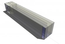
I don't understand why you're calling it a 1 note BP. The driver's rear radiation goes into the beginning of a 15ft TL, which is folded so the driver's front radiation is just inside the terminus. Here's a drawing of the straight one.
An externally hosted image should be here but it was not working when we last tested it.
Danley's version is different in that the driver radiation goes into the line 25% down from the top and also the out of phase radiation goes into the line 25% from the terminus, so the front & rear radiation are separated by 1/2 the line length. From what I read, the out of phase radiation has little effect on response, but since that side of the cone was loading into the line (instead of the room), there was less excursion allowing much high power input.
What am I missing?
Greets!
Well, the way I view it, when the driver is in compression it's an end loaded TL and on rarefaction it's a terminus driven TL, so we have a max gain BW/min gain BW situation, but 180 deg apart, so it seems to me they would sum, creating an acoustically efficient 'one note' vent, 'locking' the driver just like in a BR or TL or BP at resonance. Obviously it will have a rippling decay based on its Q, but I don't see it as being a very useful BW unless maybe if it's tuned really low, like 7-8 Hz. Only one way to know for sure though.
I just mentioned the 50% position because Joe (qi) speculated in another thread that's what TD used in the TOP sub.
GM
Isn't the effect you described going to happen anyway, at the frequency dictated by the driver offset, whatever it happens to be? I guess that's the idea, moving the gain boost away from the resonance point...
The TOP driver offset cannot be 50%, that's the end of the line and there's nowhere to mount there.
The TOP driver offset cannot be 50%, that's the end of the line and there's nowhere to mount there.
just a guy said:Isn't the effect you described going to happen anyway, at the frequency dictated by the driver offset, whatever it happens to be? I guess that's the idea, moving the gain boost away from the resonance point...
The TOP driver offset cannot be 50%, that's the end of the line and there's nowhere to mount there.
Regarding the TOP sub, notice how everything is kept kind of vague. Doesn't TD usually like to show off the great technical stuff with his designs? This one even includes the smoke screen of "special driver", with no detail at all. It leads me to believe that Jensen just missed the mark with the transflex and the TOP is just quite simple, a TL folded in half with the driver in the center of the cab.
Greets!
Right, as you move the driver along the pipe's length, its gain BW changes, trading peaking at Fp for BW.
End of the line? 50% means halfway between the closed end and terminus and if you read MJK's thoughts on driver positioning, halfway was the reasonable choice for his positive taper (horn) MLTL, though he does 'backpedal' a bit with his Classic TL driver positions, instead using a sliding scale based on taper ratio like I've recommended.
GM
Greets!
Only after his patents have been published and in the public domain. BTW, the Labhorn unit qualifies as a 'special driver'. 😉
I don't believe Jensen 'missed the mark' at all if you consider the limits of audio available to the consumer at the time of its debut. Concrete slab construction homes were coming into vogue, so there was no basement for the avid enthusiast to turn it into a subterranean Helmholtz resonant coupler for those few R-T-R tapes that had true LF content. These would fade away for a few decades and be 're-invented' as manifold IBs.
GM
You said "50% means halfway between the closed end and terminus".
Exactly. There is nowhere to mount at 50% unless you mount on top of the box (when standing up, mouth side down), but then it would just be a traditional tl with the driver mounted outside the box.
My Jensen Imperial impressed me and I now have to believe that if they designed a sub to be used from 45 hz down to ??? (maybe 18 flat or possibly lower) that it is going to perform as designed (with the driver being an arguably small variable). I am semi-happy with 45 down, but would prefer 60 and down.
My transflex project (which you helped me model for an appropriate driver for, traditional style) will hopefully be underway in a couple of days and my mounting position of choice is transflex position. In case of emergency the 25-75% tap was second choice and traditional tl as modelled is the fallback plan.
If you or anyone else has good reason to try any other alignment I am open to suggestion, but all 3 of my potential alignments are basically commercially proven designs (except maybe the traditional, which is modelled with a commercially proven program).
And what is your opinion of the idea that increased power handling is a side effect of positioning the driver a substantial distance from the mouth?
Greets!
Yeah, in retrospect, I was visualizing a two pipe system rather than a 'tapped' one.
WRT power handling, it's a fact, study up on pipe resonance theory for a much more in-depth explanation than my previous admittedly simplistic references.
For the rest, I have at least one other alignment, but I'm going to check it out myself whenever I get around to it, so for now I'm going to sit back and look forward to you telling us how well reality matches what's been published so far. 😉
GM
Do you have any material to recommend on pipe resonance theory? In my studies so far I have seen no reference whatsoever to power handling being influenced by driver offset (or alignment), only FR.
I will share my experiences freely, however I have no measurement equipment whatsoever, except for an old tube signal generator and an mp3 sine sweep from 20 kz to 20 hz.
WRT TD's TOP FR curve, the peaks and dips are clearly there in the usable FR range, the unique driver offset seems to have controlled them to a usable extent without stuffing. I am worried that the driver used could change the location of these peaks and dips, and therefore possibly negate the effects TD experiences with HIS driver mounted in HIS unique offset location.
For this reason I am partial to the transflex loading scheme. I KNOW there are going to be really dramatic FR bumps but hopefully they will be outside my usable range (hopefully above 50 hz). In this case I don't care how severe they are, I'll never hear it.
That leaves efficiency as the only benefit to the transflex loading, and the spot I want my extra efficiency is WAY down low, not to cancel the effects of the hills and valleys up top.
If this works for me as planned, the only reason I would even attempt TOP's alignment would be increased power handling, as John mentioned might be possible.
The TOP looks like an all purpose sub, that is not my goal. My goal is for HT with the lowest point of my FR curve hopefully 6 db higher than my high cutoff point.
So IMO the TOP is still an interesting side note, but unless someone tells me there is a good reason to try it (specifically increased power handling) , I'm not going to unless the transflex alignment has a serious problem with either cone excursion or FR.
Well, over at Decware audio forums, with the help of John in CR and BassBoy, we came up with an incredibly ingenius way to fit this TL into a box with only 2 pieces of wood to form the 3 folds.
It also happens that by changing the driver's mounting position, we can change from normal end loaded design to jensen transflex loading or TOP loading at 25 and 75% line length.
Here is a picture from sketchup:
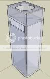
The secret is the two baffles that seperate the rectangular internal volume of the box into 4 equal area triangular colums. Then simply cut the baffles in the right spots to fold the line, and whamo bamo.
It also happens that by changing the driver's mounting position, we can change from normal end loaded design to jensen transflex loading or TOP loading at 25 and 75% line length.
Here is a picture from sketchup:
The secret is the two baffles that seperate the rectangular internal volume of the box into 4 equal area triangular colums. Then simply cut the baffles in the right spots to fold the line, and whamo bamo.
Well, It is good to see your are making progress, and that you are using Sketchup also!
A comment or two...
Triangulated tLines have been around for decades (by none other than BAILEY)
http://t-linespeakers.org/design/foldings/tttl.html
IMHO, they are not worth the additionall effort.
(the lines are VERY difficult to seal properly)
That said, I really don't see any major differences in what I proposed to you over a month ago?
http://www.diyaudio.com/forums/showthread.php?postid=913087#post913087
Attachments
I guess so now that I look back. Kinda funny. I just skipped over that because at the time the transflex and tapped line geometry weren't really interesting. Over at Decware, it just happened we could make the design so it was easily converted to either type. So why not heh?
I think this triangular line design will be much easier to construct than a multifolded line using the entire width of the box. I mean, I need to only cut 9 pieces of wood. And only 2 of those will have angles. Not to mention I will know exactly where boards are without having to draw out the design, they all meet in the corner.
Also, the line takes up less volume this way, there are only 2 pieces of wood making all the folds.
In any case, John's and your idea to easily convert between layout wills be used, I plan on testing all three geometries with the same driver amp etc.
Actually John was also aware of my renderings / posts regarding this issue.
I am glad my input was of some use here.
Properly sealing a triangulated line is a daunting task so GOOD LUCK!
(if it is not well sealed your results will be "underwhelming")
For maximum bottom-end, go with the driver on the end (no offset), and no stuffing.
(be sure to use a steep XO before the 3d harmonic)
This is what I did and I am not disappointed...
http://www.diyaudio.com/forums/showthread.php?postid=255756#post255756
Actually, neither of those designs allows for an easy change for the driver at end of line and the Danley alignment at 25%/75% from the beginning of the line. Your options are limited to end of line or at 50%. The driver needs to be at the other end of the cab for the Danley alignment.
The way to accomplish that is with triangular pathways with panels large enough for interior mounting of the driver. Rectangular pathways to accomplish the same would result in very large CSA's.
I don't understand the point about sealing. If anything the triangular shape would be easier to get into and seal the joints. I always seal joints of any cab with caulking, just to be sure, and ensure plenty of curing time if silicon is used due to the acid released during curing.
Another concern I have with both layouts is that you will need to fill some of the void in those chambers. You don't want to end up with a BR with a very long large port.
If end of line mounting is your primary plan and cab size is important, then rectangular pathways with the driver in the front panel is the way to go. It would be the easiest to fit the basket of the driver, with a spacer on the outside or a hole for the magnet in the interior panel. If you go with the extra hole, leave the nearby endcap off so you can seal around the magnet. The terminus would be in back, but if you wanted it in front, just extent the line around the end of the cab (more efficient than a box for the driver on the end.
Why would I fill the voids? wouldn't that destroy the entire point of the cab? I mena isn't it supposed to be a quarter wave tube?
Sealing triangles will be much easier I feel also.
I plan on leaving the insert (the baffles) sealed together and very tight in the box, but not fastening it to the sides. This way, I can simply pull it out and rotate it 180 degrees to try the TOP.
After testing all three designs, I will seal up and fasten the final build.
Qi, do you have pictures of your project? I did not see any in the thread, but have yet to go through it.
Your drawing has a box on the end of a very long port. The excess area of that box needs to be filled or it may not be a TL and just end up a BR with a very long port.
You can turn that plate with the hole however you want, or even use one with the hole cut to flow into another pathway and it still won't be like Danley's TOP sub. Yours is an end of line driver position and to get to a 25%/75% driver position will require the driver to be at other end of the cab.
You can turn that plate with the hole however you want, or even use one with the hole cut to flow into another pathway and it still won't be like Danley's TOP sub. Yours is an end of line driver position and to get to a 25%/75% driver position will require the driver to be at other end of the cab.
Yeah, the way it is now traditional driver mounting end loaded is really your only option. If you want to try any other options the box on the top has to go and the driver needs to be mounted in one of the triangles.
It's not entirely necessary to try anything else, as your models look really good the way they are. But John is probably right about making the box on top as small as possible to avoid BR action. Who knows, it might even be better with BR loading at the beginning of the line but it's impossible to model, so probably worth avoiding if possible.
It's not entirely necessary to try anything else, as your models look really good the way they are. But John is probably right about making the box on top as small as possible to avoid BR action. Who knows, it might even be better with BR loading at the beginning of the line but it's impossible to model, so probably worth avoiding if possible.
Relax,
You have 3 options if you want the flexibility of trying the different alignments.
1. Leave both end caps removeable and make different baffle boxes to install on whichever end the alignment requires.
2. Build your cab so driver can be installed on an interior panel. With that magnet size, you'd have to go with a larger CSA, at least 70sqin, and rectangular pathways with the interior panels in a "+" shape. Another problem is that if you end up going with a normal TL, driver outside, it would be off to the side on that widest panel.
3. Forget about end of line mounting (no real benefit anyway), leaving yourself with tapped at 25% or exterior at 25% from closed end. Qi design is probably best for this, but you'd have to fill that extra volume in the driver mounting box. Then just leave the box open on one side and plug the opening to the line on that side, for normal TL operation.
- Status
- Not open for further replies.
- Home
- Loudspeakers
- Subwoofers
- Lets do it all again: TL Sub.