I've been educating myself on crossover design, and in my searches I came across a lot of series crossover information that's very interresting. Parallel crossovers, although still very difficult to design with any sort of accuracy, are at least very easy to understand. The series crossover is a bit more abstract and not as easy for me to analyze by looking at. I found a couple posts by sreten that included some very informative pictures. Those are in the following thread:
http://www.diyaudio.com/forums/showthread.php?s=&threadid=27813&highlight=series+crossover
It made sense that the component values stayed the same. I started digging to see what else was the same. I was surprised. I redrew a couple circuits, and here's what I came up with. First is a typical first order series circuit:
Next is that same circuit, redrawn:
What's interresting about seeing it this way, is that if you simply remove the electrical connection at the "dot", you wind up with the parallel version of the same circuit. That one electrical contact point is the only difference between the series and parallel circuit.
So, I decided to redraw the Acoustic Reality circuit. Here's the original:
Here it is redrawn:
Now, if you remove that little dot, you wind up with a really interresting parallel circuit.
Now it would seem that with the conventional series crossover, you'd wind up with the same overall filtering properties as with the equivalent parallel crossover. My main source of confusion is just how that one extra connection point in the series circuit effects the behavior of the entire circuit. Series circuits have a reputation for being more forgiving if values aren't 100% spot-on, and they seem to have better impedance characteristics. Why?
Moving on... if it's safe to assume that the series and parallel circuits will provide similar results with similar components, then what about the AR circuit? What happens if you modify that into a parallel config? From the looks of it, the two inductors in the AR circuit are just combining to form one different value. Fair enough. What really boggles me is that the AR circuit is supposed to work without the capacitor, provided you change the R1 value. This is telling me that L1 in parallel with the tweeter is what's performing the high-pass functions. In order for L1 to perform high-pass on the tweeter and low pass on the woofer, the R1 value would need to be such that the tweeter and woofer have the same impedance. This of course ignores the functionality of L2 for now because I'm too lazy to do all that math. Is anybody following me here?
The similarity between the series and parallel circuits exists for higher order systems as well. It's always the same circuit, with the single connection point that separates series and parallel. Can somebody please explain to me exactly what's going on inside the series circuit that makes it so much more forgiving to slight changes in component values? What's really boggling my mind is how the AR design can supposidly work so well for so many drivers without making major component changes.
Anybody care to help me understand this?
http://www.diyaudio.com/forums/showthread.php?s=&threadid=27813&highlight=series+crossover
It made sense that the component values stayed the same. I started digging to see what else was the same. I was surprised. I redrew a couple circuits, and here's what I came up with. First is a typical first order series circuit:
An externally hosted image should be here but it was not working when we last tested it.
Next is that same circuit, redrawn:
An externally hosted image should be here but it was not working when we last tested it.
What's interresting about seeing it this way, is that if you simply remove the electrical connection at the "dot", you wind up with the parallel version of the same circuit. That one electrical contact point is the only difference between the series and parallel circuit.
So, I decided to redraw the Acoustic Reality circuit. Here's the original:
An externally hosted image should be here but it was not working when we last tested it.
Here it is redrawn:
An externally hosted image should be here but it was not working when we last tested it.
Now, if you remove that little dot, you wind up with a really interresting parallel circuit.
Now it would seem that with the conventional series crossover, you'd wind up with the same overall filtering properties as with the equivalent parallel crossover. My main source of confusion is just how that one extra connection point in the series circuit effects the behavior of the entire circuit. Series circuits have a reputation for being more forgiving if values aren't 100% spot-on, and they seem to have better impedance characteristics. Why?
Moving on... if it's safe to assume that the series and parallel circuits will provide similar results with similar components, then what about the AR circuit? What happens if you modify that into a parallel config? From the looks of it, the two inductors in the AR circuit are just combining to form one different value. Fair enough. What really boggles me is that the AR circuit is supposed to work without the capacitor, provided you change the R1 value. This is telling me that L1 in parallel with the tweeter is what's performing the high-pass functions. In order for L1 to perform high-pass on the tweeter and low pass on the woofer, the R1 value would need to be such that the tweeter and woofer have the same impedance. This of course ignores the functionality of L2 for now because I'm too lazy to do all that math. Is anybody following me here?
The similarity between the series and parallel circuits exists for higher order systems as well. It's always the same circuit, with the single connection point that separates series and parallel. Can somebody please explain to me exactly what's going on inside the series circuit that makes it so much more forgiving to slight changes in component values? What's really boggling my mind is how the AR design can supposidly work so well for so many drivers without making major component changes.
Anybody care to help me understand this?
Hi Jim,
Very interesting indeed. I'm glad you redrew the Xovers to make that more plain. If you remove the dot and allow those wires to cross without connecting, then you seem to have a parallel circuit, the only difference being that the choke and cap are on the "negative" side instead of the "positive" which doesn't matter a spit.
When they are connected, it also appears that the choke and cap act as a bypass for the opposite drivers like a 2nd order does.
Am I seeing this correctly? Perhaps others more experienced in this matter might shed some light.
Cal
Attachments
IMO, please flame me if I am wrong, series crossovers have no advandtages over parallel ones. They seem terribly much harder to design though. You really would need a simulation software and you'd really have to simulate the impedance of the drivers carefully. even more than with parallel filters. To try to understand the behaviuor other than very roughly is deemed to fail. Either build it and measure, or simulate.
Now, in the end you may very well end up with a filter just as good as a parallel one, but hardly better, and with a lot more effort.
BTW, for the first order filter, LP filtering for the woofer is mainly done by the parallel capacitor, and the LP filtering of the tweeter is taken care of by the inductor (which is effectively ruined by any series resistance in the coil).
BTW2 The redraw in your fourth image is wrong, L1 should be in parallel with the tweeter.
Probably I did not answer your question(s), but hopefully I introduced some doubts to you regarding series filters.
OK, flame me!
😱
Not really. When drawing out that schematic, I followed the same reconfiguration as I did in the single order filters above. I just redrew it in a more conventional manner.BTW2 The redraw in your fourth image is wrong, L1 should be in parallel with the tweeter.
Jim85IROC said:
Not really. When drawing out that schematic, I followed the same reconfiguration as I did in the single order filters above. I just redrew it in a more conventional manner.
Are you seriously saying the pictures 3 & 4 in you first post are equivalent? BTW3 😉 isn't the voltage source shorted when the dot is there?
Sorry, but the redrawn AR circuit doesn't look correct to me.
Only first order series crossovers have the interesting property
of changing the c/o frequency if component values are incorrect
such that the responses still sum to unity.
This makes a series 1st order crossover a good "fit it and hope"
crossover for the amateur.
And it is only the first order case where the component values
are the same for both series and parallel connection.
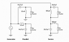
2nd order Butterworth's for 8R :
🙂 sreten.
Only first order series crossovers have the interesting property
of changing the c/o frequency if component values are incorrect
such that the responses still sum to unity.
This makes a series 1st order crossover a good "fit it and hope"
crossover for the amateur.
And it is only the first order case where the component values
are the same for both series and parallel connection.
2nd order Butterworth's for 8R :
🙂 sreten.
Attachments
sreten said:
This makes a series 1st order crossover a good "fit it and hope"
crossover for the amateur.
But what if the coil has a series resistance. Will there be much of a HP effect then?
Svante said:
But what if the coil has a series resistance. Will there be much of a HP effect then?
if you look at the 1st order c/o vertically the sum of the voltages
across the drivers and the sum of the voltages across the c/o
components, both must sum to unity.
🙂 sreten.
sreten said:
if you look at the 1st order c/o vertically the sum of the voltages
across the drivers and the sum of the voltages across the c/o
components, both must sum to unity.
🙂 sreten.
Yes, but I am more concerned about the stopband for the tweeter. I agree that the sum will be 1, but I don't think it is good that say 10% of the voltage at 50Hz goes to the tweeter.
Also, "fit and hope" can lead to a nastyly low impedance as the coil and capacitor form a series resonance circuit. Given that the impedances of the speakers are far from resistive, this is not very unlikely. The first order parallel filter has no such risk.
Ahhh... I see now that my "dot" on the redrawn AR crossover should be between L1 and L2, effectively keeping L1 parallel with the tweeter.
This whole series crossover idea is still causing me all kinds of confusion. I think I'm going to have to put it into P-Spice and plot some responses so that I can really get a good idea of what's going on.
This whole series crossover idea is still causing me all kinds of confusion. I think I'm going to have to put it into P-Spice and plot some responses so that I can really get a good idea of what's going on.
Jim85IROC said:Ahhh... I see now that my "dot" on the redrawn AR crossover should be between L1 and L2, effectively keeping L1 parallel with the tweeter.
This whole series crossover idea is still causing me all kinds of confusion. I think I'm going to have to put it into P-Spice and plot some responses so that I can really get a good idea of what's going on.
Still wrong, R1 should be connected with L1. As I said, series crossovers are a good way of creating confusion. I think you are starting to realise that. 😉 If you do the pspice simulation, make sure to simulate the drivers impedances too, don't just use a 8 ohm resistor. You can use this schematic for the driver impedance. You can skip the RML resistor.
Attachments
Svante said:hopefully I introduced some doubts to you regarding series filters.
What are the pros and cons of Series versus Parallel?
I interpret your post as saying that there are normally no advantages in using a series crossover.
Curious as to why they are sometimes used. Why do you think they are sometimes used?
Darn it, I'm just too foggy in the evenings to understand the technical stuff - and that's usually when I'm on the forums.
I was glad to see this thread in hopes of gaining a better understanding in general terms ( without schematics).
While you are indulging me (hopefully) I would be interested if somebody could in general terms explain John K's "transient perfect" crossover. Pros n cons. When I try to read his site I bog down in the schematics and technical details.
Regards
Ken L
I'm not going to get into the debate at this stage...
.. except for a couple of comment,
1. that with the right drivers, a suitable series x-o will generally have better dynamics, imaging and "musicality"
2. the simple first order series is not as hit and miss as Svante seems to imply, and so long as certain princples are followed, impedance problems will not arise (just like any other crossover)
3. for low x-o points it is very necessary to use low dcr coils, and robust tweeter, (but I have never blown up a tweeter using a series x-o)
4. If you can think of a parallel filter as a "subtractive" filter, and a series as a "bypass" filter you are part way to understanding the difference..
For further reading, here is my collection of stuff !!
http://users.tpg.com.au/users/gradds/series_cross-overs.htm
My understanding is that the series first-order network is immune to impedance changes in the drivers. I don't believe there are any mystical properties other than that. In one particular design I was working on it sounded better than a parallel network but I wouldn't dare say it would be that way for every system.
Ken L said:
What are the pros and cons of Series versus Parallel?
I interpret your post as saying that there are normally no advantages in using a series crossover.
Curious as to why they are sometimes used. Why do you think they are sometimes used?
Ohoh... This is sensitive stuff, and I'll probably be flamed for this, but you ask me what I *think* so OK: I think that in the audio business, and diy, there is a strong will to do something *different*. Given that the designer of a system is not particularly objective after weeks in the workshop, the listening test that follows the design will not be either.
Don't get me wrong here I am not saying that DIYers are stupid or anything (apart from myself, possibly), it is just that during the evoultion of DIY there will come up strange things like a sixth finger or albino rabbits. They will live a good life, but they will hardly be better than the normal rabbits. Most of the things that are different will be less than optimal, but sometimes the evolution invents the eye! The serial filter is *not* an eye.
To get back to series vs parallel crossovers, I think that parallel crossovers are much easier to understand but that they in the end can be *equally* good. The only reason I see to use the filter that is harder to understand would be social (marketing, showing off etc), not technical.
That is what I think, others will think differently, and that is OK IMO.
I can appreciate the idea from sreten that the first order series filter always will sum up to one, though, but that is as far as I'll go 😉
Ken L said:
Darn it, I'm just too foggy in the evenings to understand the technical stuff - and that's usually when I'm on the forums.
I was glad to see this thread in hopes of gaining a better understanding in general terms ( without schematics).
Sorry about the schematics, I can't help myself. I do beleive that one has to understand them in order to make any sense of filter design, though.
Ken L said:
While you are indulging me (hopefully) I would be interested if somebody could in general terms explain John K's "transient perfect" crossover. Pros n cons. When I try to read his site I bog down in the schematics and technical details.
If I may, I suppose that the term transient perfect would originate in that the two branches of a first order series filter sums up to one. If the drivers were ideal, a filter transfer function of 1 would lead to perfect transient reproduction.
Yes, but I am more concerned about the stopband for the tweeter. I agree that the sum will be 1, but I don't think it is good that say 10% of the voltage at 50Hz goes to the tweeter.
True, note 10% voltage = 1% power, but low DCR is a must.
Also, "fit and hope" can lead to a nastyly low impedance as the coil and capacitor form a series resonance circuit. Given that the impedances of the speakers are far from resistive, this is not very unlikely. The first order parallel filter has no such risk.
Basically referring to people assuming 8 ohm resistive loads
for their crossover calculations. Parrallel will be wrong,
Series will still sum to 1 but have a different c/o frequency,
a litttle higher.
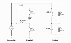
The 1st order series doesn't need a zobel on bass / mids.
The 1st order parallel does to be accurate, or at least
subtracting units inductance from the inductor.
(1khz c/o 8R resistive load)
🙂 sreten.
Attachments
Svante said:sixth finger or albino rabbits. They will live a good life, but they will hardly be better than the normal rabbits. 😉
Heh heh heh
Svante said:Sorry about the schematics, I can't help myself. I do beleive that one has to understand them in order to make any sense of filter design, though.
Posting of schematics is not a bad thing at all. No need to apologize. That was my way of saying I have problems with them.
sreten said:
The 1st order series doesn't need a zobel on bass / mids....
🙂 sreten.
Would you say that an advantage of first order series crossovers is that they stabilize (flatten) the impedance of the drivers??
Thanks for your responses guys, I find this to be an interesting thread.
Regards
Ken L
Ken L said:
Would you say that an advantage of first order series crossovers is that they stabilize (flatten) the impedance of the drivers??
Regards
Ken L
I'd say the advantages of series 1st order if the drivers are
suitable and have flat responses, it is difficult to end up with
a non-flat response.
Its disadvantage is that it can't be deliberately misaligned.
In a first order parallel crossover you could for example
play with the mid inductor value to compensate for a rise
towards the drivers top-end, or a lack of top end.
With a series 1st order you can't do this.
🙂 sreten.
Correcting a few misconceptions...
1. it is generally best to use a zobel in a series x-o. this stabilises the impedance of the woofer. The values used do not have to be normal "zobel" values and can in fact be used to alter mid response.
2. It is possible to deliberately misalign the series x-o.. Doing this in the right way can be used to counteract rising or falling woofer responses. But things sill happen in a "smooth" way.
3. Drivers in series x-o do not have to have equal impedences, and do not have to use normal "Butterworth" values as seems to be indicated in the original post.
If you read point 2 on the following page, you may realise that there are reasons why a series x-o can often outperform a
parallel in terms of dynamics and "natural" sound.
http://users.tpg.com.au/users/gradds/series_cross-oversJR.htm
- Status
- Not open for further replies.
- Home
- Loudspeakers
- Multi-Way
- Let's discuss series and parallel crossovers