Lol, so that was a daft question of mine earlier 😀 Whats the main chip... told you I don't do Class D. But no matter......
EDIT:
In my haste I didn't notice that a Mod had to approve my posts. Sorry for the double/triple posts.
In my haste I didn't notice that a Mod had to approve my posts. Sorry for the double/triple posts.
Last edited:
No worries, I'm learning as I go along, so no doubt I'll be asking dumb questions.
On the chip it reads: Tripath A2020-020
On the PCB: LEPY LP-2020A. 130416PCB
Thanks for the help
On the chip it reads: Tripath A2020-020
On the PCB: LEPY LP-2020A. 130416PCB
Thanks for the help
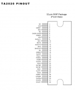
Here is the pinout
Thanks, Pano! That's much easier for me to read than the Schematic I was looking at. Might well have been Hieroglyphics for all I know.
The pins are staggered, how do I go about counting them? Also, which ones do I need to test for faults and what have you?
I really appreciate all the help. I've never had such quick replies on a Forum before.
You're welcome!
I'd say the first test is to see if there is any voltage on the speaker output pins.
You should see very little to no DC voltage between the +/- speaker pins.
Both + and - (red and black) should read about 6V DC to ground if the amp is running.
Normally you should see 1/2 the supply voltage on both speakers terminals, both neg and pos.
Check that first.
And be careful not to accidently short any pins out. That would be a disaster.
I suspect the majority of faults will come down to the main IC on this amp but you should always check the basics as Pano has pointed out.
I suspect the majority of faults will come down to the main IC on this amp but you should always check the basics as Pano has pointed out.
I still can't figure out the pin configuration. My board has 4 pins not connected.
Just done testing. Tried to get a reading from the terminals, nothing. So I went along all the pins with the Multi Meter. A picture is worth a thousand words so I made a crude paint document of what each pin is putting out. All the others are not reading voltage. I also tested all the caps following along from the power jack. All give a 12v Reading as does the power supply itself.
Just done testing. Tried to get a reading from the terminals, nothing. So I went along all the pins with the Multi Meter. A picture is worth a thousand words so I made a crude paint document of what each pin is putting out. All the others are not reading voltage. I also tested all the caps following along from the power jack. All give a 12v Reading as does the power supply itself.
An externally hosted image should be here but it was not working when we last tested it.
If you look at your picture then top left (n/c no connection) is pin 1, the one circled pin 2 etc. So pins 2 and 8 are joined by PCB print. I reckon the chips duff unless there is a standby mode etc. I'd have to see the full circuit to know that and I notice pin 17 is marked sleep... but instinct tells me the chips dead.
OK, from squinting at the picture pin 17 (sleep) seems to go to ground so that means its not used. That reinforces the faulty chip scenario.
If you decide to replace it then its not difficult to remove, but ask first as there are ways and means to do it without damaging the print 🙂
If you decide to replace it then its not difficult to remove, but ask first as there are ways and means to do it without damaging the print 🙂
Yep, if you are not getting any DC between the speaker terminals and ground, the amp is not running.
Maybe a bad chip, but they don't often blow up.
Maybe a bad chip, but they don't often blow up.
You should also be seeing 5V DC at pins 10 & 13. Those are the input pins, they connect to the input caps, if you know where those are.
No worries, I'm learning as I go along, so no doubt I'll be asking dumb questions.
On the chip it reads: Tripath A2020-020
On the PCB: LEPY LP-2020A. 130416PCB
Thanks for the help
This is a relatively new amp manufactured after 16 April 2013. Currently I am receiving LP-2020A+ amps made after 8 May 2013. So far so good.
Saturday's update: The now R-3C-R-2C-R-2C "Pi" filter spliced into the wire from Switching PS to the LP-2020A+ seems to be working OK.
The amp is drawing about 16 watts, with my ~8 ohm speakers.
The PS that came with my amp is rated 12V 3A. I measure 12.75V, unloaded, at the plug, 12.68V with amp connected and turned on.
With the filter in, I measure 11.86V with the amp set as high as the Volume knob will go without ever cutting off... I use the Realtek HD Audio Manager to adjust the actual listening level. The Amp Volume knob is just to limit my enthusiasm to the Reality of the amp's limit, given the supplied PS and my homebrew PS filter.
I still have not opened the amp case... yet.
I have located 5A 0.01 ohm DCR ferrite looped wire 835 ohm 100MHz chokes for $4.12 for ten each at Digi-Key. Seem OK. Comments? For output stages?
Digi-Key Part Number: 240-2491-ND
I am still groping a bit in this world were the entire amp draws less voltage/current than some tube's filament. But, the Music is delightful.
Another Saturday 🙂 The Hi-Pi Hi-Fi Power Supply filter is now:
10uF 630V PP/Oil Can Cap
-
500 mOhm 10W Resistor
-
3300uF 63V TS-HA cap
+
2200uf 35V TS-HA cap
+
2.2uF 630V PP cap
-
500 mOhm 10W Resistor
-
10,000uF 50V TS-HA cap
+
0.01uF 630V PP cap
-
8 Ohm 25W resistor
-
10,000uf 50V TS-HA cap
+
2 uF 630V PP/oil can cap
into the Lepai LP-2020A+
The Resistors are each in series with the Positive (+) wire.
The Caps are each in shunt to the Negative (-) wire.
The Voltage ripple is calculated at less than 10 uV.
The Current ripple is calculated at less than 250 nA.
Reasonably stiff and quiet supply.
Marian McPartland Trio: "Live at Shanghai Jazz" sounds awesome.
Great chops 🙂
Happy Ears!
Al
Yep, if you are not getting any DC between the speaker terminals and ground, the amp is not running.
Maybe a bad chip, but they don't often blow up.
I respectfully submit that the OEM ta2020 chips were 'fairly' stable. Not outstandingly so though.
However..those oems.. have been extinct for some years now.
Current production is seemingly from any number of cheap/inept Fake makers . Recently bought 'guaranteed' OEM ta 2020 chips from Eljer.
These showed up featuring Gold plated pins 🙄
Simply Too much trouble to chase after the Liars' claims.
IMO Tripath, No Longer exists in any resemblance of it's former self.
I did some more measurements, to show my brains are not just for enjoying great sound.
My Amp is idling at about 5 watts in from my power supply. It is about 80% to 88% efficient. So, the are about 4 watts available for the speakers to ingest. I assume they each time share the same 4 watts, so they can advertise 8 watts to the consumers.
My woofers can do about 98 dB at 4 watts. Adequate for my bedroom.
Isn't arithmetic much more interesting than Music?
Happy Ears!
Al
Hi, my lepai amp have died when i was not using it. It workt for a cuple om weeks ago, but nu it only ticks.
I have read alot of this tread but not found an answer.
My exp with this cind of fluff is very limited, what shoud i check first? I have pocked around a bit on the pots and other things inside it to se if it would start to work.
I have read alot of this tread but not found an answer.
My exp with this cind of fluff is very limited, what shoud i check first? I have pocked around a bit on the pots and other things inside it to se if it would start to work.
- Status
- Not open for further replies.
- Home
- Amplifiers
- Class D
- Lepai T-Amp with TA2020