I know exactly what you mean 😀 . . . and this is no way to stop the hate-mail!That depends on the female.
Old, cheap, surplus . . .
Seriously, are LEDs noisy?
SY said:No, they're very quiet. I use one to bias the first stage of my MC phono preamp.
What an interesting use for hatemail. 😀
SY said:Both. Have an LED to keep the Vgk constant. Have a CCS in the plate to keep ip constant. This will generally minimize distortion.
Not quite what I mean.
With a led you get steady bias and consequently (hopefully) absolute control over the cathode current. With a bypassed CCS in the =cathode= circuit you get absolute control over the cathode current without the intermediate step of setting a particular bias voltage.
What is most desirable? Correct bias voltage but indeterminate cathode current because of variations in one tube to the next (or as the tube ages), or correct cathode current by whatever bias voltage it takes???
What is most desirable? Correct bias voltage but indeterminate cathode current because of variations in one tube to the next (or as the tube ages), or correct cathode current by whatever bias voltage it takes???
AsI pointed out, you can have your cake and eat it, too- plate and cathode currents are normally equal, so by setting Vgk fixed, the only thing that needs to be varied to make sure that current is what you want is the plate voltage. And the CCS does that automatically, including taking care of tube aging.
SY said:
AsI pointed out, you can have your cake and eat it, too- plate and cathode currents are normally equal, so by setting Vgk fixed, the only thing that needs to be varied to make sure that current is what you want is the plate voltage. And the CCS does that automatically, including taking care of tube aging.
In addition to having cake and eating it, you also get some for friends. I use this basic schematic, and in addition to the low distortion and easy bias, you can drop all sorts of tubes in the front without a change.
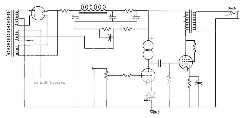
For instance, with the bias at ~2V and the current at 12mA or so, you can (changing the heater wiring a bit with a switch) use a 12au7, 12at7, 6dj8, 6n6p, 6h30p, 6cg7, and about 50 other variants thereof. Makes for a fun little amp with adjustable gain and sound.
-d
There's even a few slices left over for passers-by: the plate CCS load dramatically improves power supply rejection.
For instance, with the bias at ~2V and the current at 12mA or so, you can (changing the heater wiring a bit with a switch) use a 12au7, 12at7, 6dj8, 6n6p, 6h30p, 6cg7, and about 50 other variants thereof. Makes for a fun little amp with adjustable gain and sound.
for once we have a topology that functions just like an SS one, i mean "tube personality" is lost in the circuit...
one more reason to write hate mails to SY.....😀
arnoldc said:Hi Tony, I find your comment interesting.. Can you elaborate?
Hi arnold,
I find above 2 posts of dsavitsk, and SY as self explanatory, and that is what i reacted to.
SS devices like mosfets and transistors have inherently higher transconductance than tubes, such that certein tolopologies can be designed to work with not just a particular type transistor, with minimum beta as basic requirement. Unlike with tubes, designs evolve around a specific tube type/s.
based on my experience with repairing solid state amps, i am able to replace/subtitute types at will with little or no observed ill effects.
I take my hat off to SY for being practical, with his LED, CCS and mosfet follower, they all make sense to me.
Ah, .. a timely thread.
You see, I'm pondering how to bias this SV83 SE (RH84 design) junkbox amp I'm building. I was about to use a grid battery bias (-3v, Li button cell) until I actually looked at the relevant tube curve (I'm clamping the screen voltage at 150V with a VR150 gas tube). Plate voltage will be somewhere between 250V and 300V once I wire in all the tubes.
Would a cathode bias using a red LED @ around 2 V (or a bunch in parallel) be safe and work better to improve the power output and current through the tube? I'm hoping not to blow this amp up 🙂
Thanks, ..
An externally hosted image should be here but it was not working when we last tested it.
Sorry if this question is obvious for the experts here, but I am a novice with electronics and just coming to terms with the very basics of tube amplifier design and theory. I have built TubeLab's SimpleSE which uses a constant current source for the driver plate, but I pretty much just followed the instructions without completely understanding the concepts. I am now in the process of building a point to point ECL82 project and am trying to understand the concepts.
I think that I understand the use of an led for the cathode bias, instead of calculating the voltage drop required and calculating an appropriate resistor, we can use the known constant voltage drop of an led to set cathode bias (?).
Now the difficult part (for me). If we use a constant current source on the plate, does that mean when we plot the load line on the plate characteristics graph, we determine what current the constant current source will regulate to and essentially plot a horizontal line on the graph (constant current at plate) instead of a sloping line that plots changing current with changing voltage drop across a plate load resistor? As the horizontal line will intersect the grid voltage lines at a more acute angle, this will allow a greater plate voltage swing for given grid voltage swing compared to a resistor load at the plate. Have I got the concept right or am I completely off track here?
Lastly, any good tips/links/rules of thumb for designing/implementing such a circuit?
For example, if I was using an ECC83 driver with B+ of around 300V. The load lines look like 1 mV biased at around 1.5-1.75 volts might be OK (if my assumptions above are correct).
Don't expect anybody to waste their time spoon feeding me answers, but any pointers would be most welcome!
Cheers,
Chris
If we use a constant current source on the plate, does that mean when we plot the load line on the plate characteristics graph, we determine what current the constant current source will regulate to and essentially plot a horizontal line on the graph (constant current at plate) instead of a sloping line that plots changing current with changing voltage drop across a plate load resistor?
That is precisely it. The horizontal load line maximizes gain and lowers distortion by reducing the effect of curve bunching at one end of the loadline. If you bias up an ECC83 with a cheap red LED and use a 0.75-1.0mA CCS as the plate load, the distortion is astonishingly low. The difficulty is to maintain that low distortion when driving the next stage...
Thanks (again!) for the input and help Sy. Don't suppose you have any suggestions for constant current devices?
Thanks again...
Chris
Thanks again...
Chris
chrish said:Thanks (again!) for the input and help Sy. Don't suppose you have any suggestions for constant current devices?
If a single 10m45 is good, then two must be better. 🙂 Try this: http://www.diyaudio.com/forums/showthread.php?postid=1222281#post1222281
(you can use 10M45's as drop in replacements for the DN2540N5, though a lot of people claim the DN2540 works better here -- the former are available at Digikey, the latter at Mouser.)
I'm nervous about the DN2540 in very low current applications, just because I haven't experimented much with it- 2540s in cascode work superbly well at 10mA or more. For my ECC83 tests, I used the "diyAudio/Morgan Jones" bipolar cascodes.
SY said:I'm nervous about the DN2540 in very low current applications, just because I haven't experimented much with it- 2540s in cascode work superbly well at 10mA or more. For my ECC83 tests, I used the "diyAudio/Morgan Jones" bipolar cascodes.
Good point -- I haven't tried it below 10mA either. Just be careful about the voltage rating on the transistors in the MJ CCS.
chrish said:Thanks (again!) for the input and help Sy. Don't suppose you have any suggestions for constant current devices?
Thanks again...
Chris
I am curious as well. What about the Siliconix CR__ series of FET current regulators?
- Status
- Not open for further replies.
- Home
- Amplifiers
- Tubes / Valves
- LED in cathode