Hi, I'm a 16 year old who has just gotten into tube electronics, and I've been trying to design a HiFi oriented push pull amp based around parts I have already. Most of them came from an old Hammond organ amp, including the 6V6s
So far, I've tried to design an output stage and a driver, but I'm wondering if I'm going to need more gain. I wanted to design this amp mostly myself to get the hang of tube theory and how it works. I've been using the valvewizard.co.uk site, which has been very helpful.
I would like input on my design so far, like what I should change, and what I've done right. I did try and draw some loadlines, which I think has gone alright. I can scan them and attach them if anyone wants to see.
I know what transformer I'm using, but haven't designed a power supply yet, so the voltages are just marked using connection arrows.
My main worry is about needing more gain. I'm guessing I should add another tube like a 6C4 to act as my phase splitter and use both of the 'AX7 stages for gain?
Thanks for your input!
View attachment Schematic.pdf
> wondering if I'm going to need more gain
For what?
For the 4V signal from an organ console? For the 100uV signal from a guitar-playing flea?
This is the 21st century. (All your life!) One reference signal is the 2Vrms 2.8Vpk out of a CD or DAC. Each side of the 6V6-team needs ~~28V peak. So you need gain of 10. You have gain of 50.
You do realize that "hi-fi" normally implies low impedance speaker drive, damping? But the plate of a 6V6 is high impedance.
There is NO shame in reading-up what was done before you.
https://www.americanradiohistory.co...Radiotron-Designer's-Handbook-3rd-Edition.pdf
PRR pointed out a key flaw. Full pentode mode finals exhibit very poor damping factor. Also, distortion levels will be unacceptably high. Both defects are dealt with by incorporating loop negative feedback (NFB) of some kind.
Dig into the archives for "Baby Huey", "Red Light District", and "El Cheapo" to get ideas about implementing the essential NFB.
Dig into the archives for "Baby Huey", "Red Light District", and "El Cheapo" to get ideas about implementing the essential NFB.

Hi and welcome, IlikeTech!
Your schematics looks good so far. The 1st 12AX7 stage provides enough gain for, say, a CD player as the input source and even allows some global negative feedback to increase damping factor and linearity and decrease distortion.
What else did you pull from the Hammond? Which model was it? Do you also have the power transformer and the rectifier? Then I'd advice you to copy just the PSU part of the organ, using new filter electrolytics, if possible.
If you have the organ's schematics, too, you could have a glance at the power amp section to get some hints how the GNFB loop can successfully be arranged around the output tranny.
Good luck!
Edit: Please avoid repurposing these old wax paper capacitors that most probably were in the organ. They're leaky after all the decades. Buy modern and reliable foil caps, they aren't that expensive.
Last edited:
Thanks everyone for your replies, and PRR, it's good to see another Mainer!
Sorry, I guess I didn't give enough information, but what has been said does confirm that a single 12AX7 should be fine. I'm trying to drive it off the signal from my phone, which is about 2.2 volts pk-pk. Also, I have been doing reading, and I do know I need negative feedback, I just forgot to add it.
I guess I will copy the organ's power supply more or less, as I have the power transformer and rectifier from it. I already have some new Nichicon 22uf 450v capacitors on their way from mouser, and all of the caps when I build will be new polypropylene and/or mylar caps.
Forgot to mention it, but the organ amp was an AO-29, and I do have the schematics, so I have been looking at them to see how things are hooked up. Interestingly, It did have an input for a radio, which is after 2 triode gain stages, one being a 12AX7, and the other being an AU7 as the phase splitter. It's only one half of each of those tubes however.
I guess I'll go read up on GNFB and damping factor. I really appreciate all of the replies. I will try to make some changes and then post my schematic again.
Also, maybe HiFi is the wrong word. I just want it to sound satisfying and be a fun project. I'm pretty sure I can't tell if something really sounds as it "should", just if I like the sound. In fact, I have a Radio Craftsmen 500 monoblock amp to fix up at some point, and that thing is truly HiFi.
Thanks, IlikeTech
Edit: What's the best place to buy an assortment of 1/2 and 1 watt resistors? I have every value of 1 Ω to 10M Ω in 1/4 watt, but I've heard that they can't take the voltage even if the wattage is enough.
Last edited:
Edit: What's the best place to buy an assortment of 1/2 and 1 watt resistors? I have every value of 1 Ω to 10M Ω in 1/4 watt, but I've heard that they can't take the voltage even if the wattage is enough.
Having just started down the same path as you, it is nice to have some reasonable selection of parts on tap. I bought a full set of 1/4 watt resistors, but ideally I should have had 0.6W ones. I have picked up some cheap 100's of a local auction site, so have most values now that are useful, and can always combine pairs if I have too.
90% can be achieved with 0.6W, so I think it is safer to go for the higher wattages as you need them, and if you buy 10's or 20's then you will have some spares if you find they are in common use.
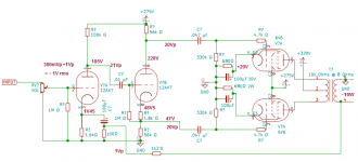
Made some changes, two cathode resistors, NFB.
And noted voltages to be expected.
Hope it will help.
Mona
Thanks, I'll look over them and do reading about the changes made to see why they make sense! Having the voltages is helpful!
You will occasionally need 1W and 2W resistors - I mostly use a 1W assortment. Here's 480 1W resistors for $10: https://www.amazon.com/WINGONEER-48...att+resistor+assortment&qid=1587667822&sr=8-7
Series or parallel if you need 2W.
Series or parallel if you need 2W.
Series adds wattage ratings as well? I didn't know that.
I'll order a 1/2 watt and 1 watt resistor assortment on amazon.
Is it okay to have the volume control like I have it? Just as an attenuator on the input?
I'll order a 1/2 watt and 1 watt resistor assortment on amazon.
Is it okay to have the volume control like I have it? Just as an attenuator on the input?
Volume control is ok.
Two resistors parallel, devided current and same voltage.
Two in series, devided voltage and same current.
And P = V x I so less current or less voltage same result on power.
Mona
Two resistors parallel, devided current and same voltage.
Two in series, devided voltage and same current.
And P = V x I so less current or less voltage same result on power.
Mona
Oh, to avoid possible scratching noise from the volume control, I'd put a 100 nF coupling cap between the pot and the grid leak.
Best regards!
Best regards!
Another vote for wiring the 6v6 as triodes. I tried pentode with heavy (20db) feedback once but zero feedback triode was definitely a better sound. Of course, using surplus gain for feedback is still welcome in triode mode, if needed.
I guess I may try it either way, both triode mode and tetrode mode, as it isn't hard to change between. Do I have to adjust my bias point for triode mode?
Thanks for the tips on the volume control, will add that cap.
Thanks for the tips on the volume control, will add that cap.
Ketje, in the schematic you modified, what is the reason for injecting feedback into the cathode bypass capacitor, instead of directly into the cathode? Most designs I've seen do it directly into the cathode.
Thanks!
Thanks!
I didn't. The feedback voltage is developed over the 100Ω resistor and passed to the cathode via the capacitor.The other resistor is only for getting a bias voltage for the triode.Ketje, in the schematic you modified, what is the reason for injecting feedback into the cathode bypass capacitor, instead of directly into the cathode?
Like that the feedback circuit is on ground level to be connected to the speaker output, with another resistor to get the wanted level.
Now we have the feedback between cathode and ground, the input between grid and ground.The tube will amplify the difference, that is the grid-cathode signal.
Mona
Have you already bought output transformers? I might suggest an ultra-linear circuit since it makes for a pretty simple handling of the screen grid but you'll have to get transformers with the required taps.
He told us quite in the beginning that he's got a set of transformers and tubes from a scrapped Hammond organ (a M-100, I believe). While I really don't appreciate scrapping a tonewheel Hammond, I like the idea of starting with parts that are already available. 'Cause that's the way most of us also started their electronics adventure 🙂.
Best regards!
Best regards!
I guess I may try it either way, both triode mode and tetrode mode, as it isn't hard to change between. Do I have to adjust my bias point for triode mode?
In theory yes, in practice not always. Especially if you use cathode bias. A general rule of thumb is that the bias voltage will be the screen voltage divided by the amplification factor (10 in a 6v6 IIRC).
- Home
- Amplifiers
- Tubes / Valves
- Learning Tubes, trying to design a HiFI oriented PP 6V6 amp