In a different thread the grid leak resistor was discussed and it was pointed out to me that the 12ax7 max value should be 100k, (I think it was a discussion about Miller capacitance and frequency roll off in a 12ax7) yet in this design we are using 1M.(R1 and R6) I know my theory is weak so could someone please explain what I am obviously missing.
IlikeTech,
and
Blaxshep,
Now, what I missed on the schematic in this post:
A 1 Meg volume control and a 12AX7 / ECC83 will have severely rolled off high frequencies.
That needs to be changed.
What what Blaxshep was missing was:
Maximum grid resistor 1Meg (to take care of grid leakage current).
But . . .
Driving impedance 10k (to take care of miller effect capacitance).
Use a signal source that is 10k or less output impedance.
Actually, with 1.5pF plate to grid, and maximum gain of 100, that is 150pF maximum miller effect capacitance.
150pF is 10k of capacitive reactance at 106kHz (- 3dB).
Even if the gain is equal to u (100) you can use a driving impedance of 2.5 x 10k (25k), and be -3dB @ 40kHz.
I hope all your signal sources have an output impedance of 25k Ohms or less.
I use 50k volume controls for all my amplifier inputs, and their first stage gain is never larger than 40, so the miller effect capacitance is 60pf or less.
Last edited:
Ok so it is really just impedance matching then. I don't want to hijack IlikeTech's thread, but I have to ask, in my case I am coming off a Mosfet 1st stage with an output impedance of 1M (The input is 10M) so a 1M grid leak is appropriate at the second stage tube input?
I hope all your signal sources have an output impedance of 25k Ohms or less.
I use 50k volume controls for all my amplifier inputs, and their first stage gain is never larger than 40, so the miller effect capacitance is 60pf or less.
Thanks for the advice! For testing, I don't actually have a volume control, the audio input is just tied to the grid and grid leak resistor on the 'AX7. I will use a smaller volume control when I build in my chassis. I'm using a headphone out from my phone, so I would guess that it has less than 25k output impedance.
Blaxshep,
1 Meg is appropriate for a good 12AX7/ECC83.
Other tubes have other required maximum grid resistors.
Look at your data tube specs, maximum resistance as appropriate for self bias, fixed bias, etc.
(DC resistance, not AC driving impedance).
1 Meg is appropriate for a good 12AX7/ECC83.
Other tubes have other required maximum grid resistors.
Look at your data tube specs, maximum resistance as appropriate for self bias, fixed bias, etc.
(DC resistance, not AC driving impedance).
IlikeTech,
The only headsets that might be able to approach 25k Ohms even at mid frequencies are the old Brush Crystal Headsets.
Most consumer headsets are from 32 to 600 Ohms. The phone can drive those, it can certainly drive a 50k volume control.
The only headsets that might be able to approach 25k Ohms even at mid frequencies are the old Brush Crystal Headsets.
Most consumer headsets are from 32 to 600 Ohms. The phone can drive those, it can certainly drive a 50k volume control.
I've decided to forgo a volume control for the moment anyway, as the phone has a volume control and I don't really need two.
So with the 1.2K ohm resistor for NFB connected, and a 1000 pf in parallel with it, the amp appears to be oscillating at a high frequency. This is in pentode mode with about 340 volts plate-cathode. It works fine without the feedback loop connected, but I would prefer to have it for obvious reasons. Should I try less feedback?
Thanks!
Your amplifier has medium gain, large gain 12AX7 input stage, less than unity gain on the concertina, low gain on the 6V6 Beam Power tubes that are in Triode Wired Mode, and less than unity gain on the output transformer. The total of all that is medium gain.
And, there is high frequency shift (lag at high frequencies) in the output transformer.
If the phase lag reaches 180 degrees at a high frequency before the gain drops to unity,
You have an oscillation.
Part of what changes the phase is the load (loudspeaker impedance phase angle versus frequency).
Your negative feedback is global, it wraps around the output transformer.
You need to do a study of the open loop gain and phase versus frequency.
Negative feedback is tricky.
I do not see a dominant high frequency pole on the input stage.
A series RC network from the first plate to ground might be needed.
Your dominant high frequency pole probably is the output transformer.
Just for fun, put a 100k resistor in parallel with the 1meg grid resistor from the input grid to ground.
I think the Miller Effect may be leaving the input grid too free to be influenced by the plate.
I wonder if that effects the results of negative feedback at the cathode.
I work hard on my designs, to make my amplifiers sound pleasing without any global negative feedback.
But they probably do not sound good on some speaker models.
Last edited:
This oscillation is happening at 1khz. I found that if I bypass the feedback resistor with a 3.3 nf capacitor, it cuts all of the oscillation as long as the input signal isn't too strong. If it is, it goes right back to oscillating. Adding a 100k in parallel with the input grid resistor didn't seem to do anything.
So, I changed back to triode mode, because it sounds way better, even with no feedback loop. I tried to do the math to get output impedance, and got two different numbers, 8.5 ohms, and 11.7 ohms. Which is more likely to be correct?
Thanks!
Thanks!
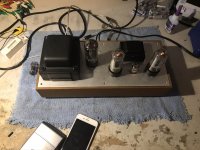
Wow, it's been a really long time since I've posted about this! Well, I finished it! I think it looks awesome. My dad made the case, and I think it looks excellent!
The top part is a routed aluminum plate, we cut a template with our laser cutter, and then routed it by hand. The case is made with teak, and the bottom has an aluminum mesh. The inside is covered with copper tape for shielding reasons, and all the metal parts are grounded.
You might notice the tubes that are installed are not 6V6s. Well, as it turns out, my 6V6s are kind of dead. I think I need to buy a new matched set, so in the mean time, I was experimenting with 6L6s. Sounds good to me! Also, disregard the 12AT7 that's installed.
Attached are some photos! Thank you to everyone who gave me advice on this project, I really appreciate it!
Thanks, IlikeTech


Looks nice.
Is your power transformer strong enough for the double heater current 6L6 900mA versus 6V6 450mA ?
Mona
Is your power transformer strong enough for the double heater current 6L6 900mA versus 6V6 450mA ?
Mona
- Home
- Amplifiers
- Tubes / Valves
- Learning Tubes, trying to design a HiFI oriented PP 6V6 amp