If you only care about 300 Hz and up, which is where Nate achieved directivity, then 6" of fiberglass spaced 2" from the wall will do nicely. Considering the system solution, I would use more than that to help tame longitudinal room modes.
Not to say I don't appreciate Nate's good work; he may well have a room where the simple low tech approaches like absorber or baffle wall don't apply.
Actually, what I've got has forward directivity closer to a dipole.....so it's narrower than a cardioid. This was my main goal due to my narrow room and asymmetrical side walls. As you say it works best above 300hz. Rear rejection on mine is only about -10dB to the rear below 300hz which measures slightly better at the lp than a sealed cab. To get better rear cancellation (and true cardioid behavior) I'd need more damping and would need to move the vent more to the rear.......which of course will widen the pattern higher up where I'm trying to keep it narrow. That's the thing with these passive resistance boxes, you can really only optimize them for a couple octaves if you're lucky. I'm considering adding an active rear driver to get better rear cancellation down low. I've been thinking since I started building these types of enclosures to do an all active version with 3-4 channels of DSP per midrange for an even narrower pattern and greater rear rejection (like the Beolab 90), but that's pretty ridiculous for a mid covering 80-1khz 😱
Alright. I might be able to squeeze in two 8" drivers if they are rear mounted and have a small basket (less than 210 mm diameter). I've found these two candidates:Yes it does. However, unlike at bass frequencies, you are more likely to run into thermal issues before you run in to problems with respect to excursion. Remember that for the same acoustic output excursion doubles for every halving of frequency. At low frequencies you need very little power to get a driver to its xmax. If you want to drive a typical hifi 7" driver to xmax at 100 hertz you might need 150 watts or more.
If your design requires large excursions (think more than about 8 mm p-p), I would advise using 8" drivers instead. You not only get more volume displacement, you also get a greater distance between front and back, for less cancellation.
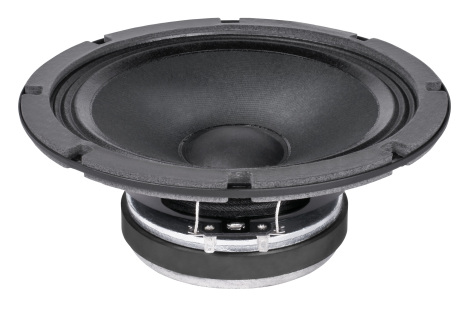
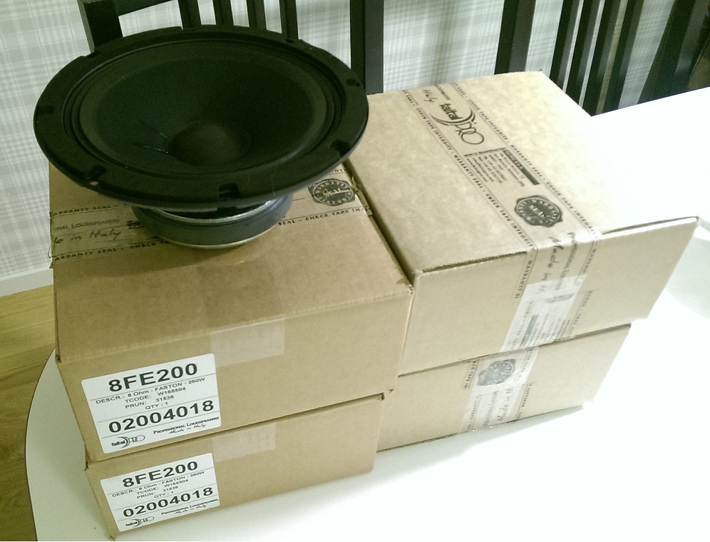
Faital Pro 8FE200
Fs: 80 Hz
Sensitivity: 95 dB (1 W/1 m)
Xmax: 4.7 mm
Nominal power handling: 130 W
Rear mountable
Cheap
Eminence BETA-8A
Fs: 65 Hz
Sensitivity: 95 dB (1 W/1 m)
Xmax: 3 mm
Nominal power handling: 225 W
Rear mountable
Slightly expensive
Used by Jeff Bagby in the Fusion-8
Thanks for the warning! I'll use something else as soon as I intend to use it (not just measuring).Never use fiberglass in a vented enclosure.
Open the curtains so the sun shines across your speakers and you will see little sparkles on every drum beat 😱.
Dan.
/Anton
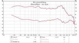
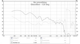
Measurements of speaker with glassfiber as flow resistance
Now I've done some measurements of this:
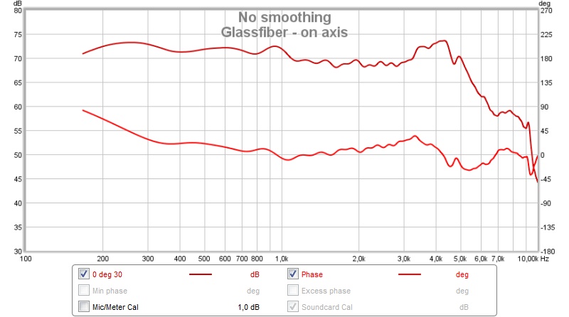
Response at 1.5 m distance, 1.5 m height (as before), 0-180° with 30 degree increments:
Compared to the earlier measurement (without flow resistance):
Verdict: Smoother response, separation down to 100 Hz, less of a hump at 180 Hz.
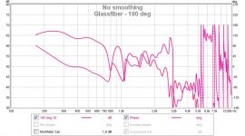
Here is phase response (gated 5 ms) for 0-180° with 60 degree increments:
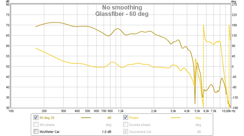
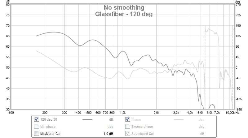
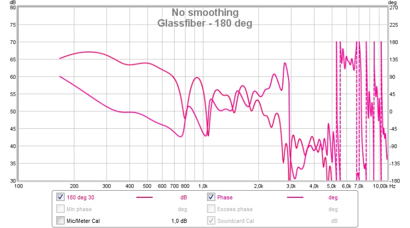
Nothing strange as far as I can see (except maybe the phase at 180°).
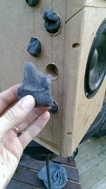
As the response was better with flow resistance I decided to add some more by putting tufts of this:
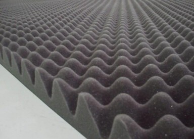
into the holes:

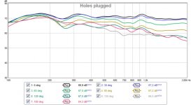
Resulting response:
Not better, too much resistance? The material has a very high flow resistance compared to the glass fiber.
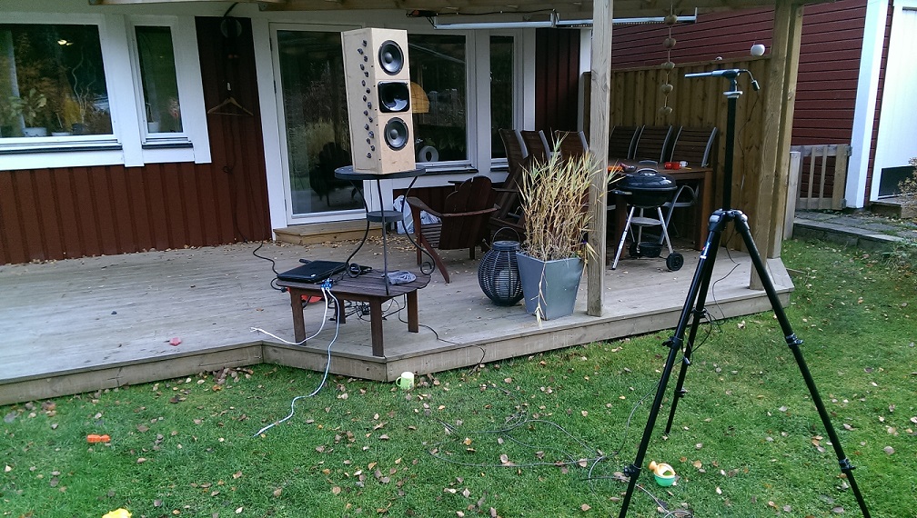
This is my measurement setup:
Just a thought: I think the result is already pretty close and I'm using no PEQ and two 5" drivers. Why am I not seeing any fall off for low frequencies (except below 150 Hz which is fine anyway)? Ramp it up to 7-8" drivers and a few more holes (twice as many?) and the result should be quite decent, right?
/Anton
Now I've done some measurements of this:
Response at 1.5 m distance, 1.5 m height (as before), 0-180° with 30 degree increments:
Compared to the earlier measurement (without flow resistance):
Verdict: Smoother response, separation down to 100 Hz, less of a hump at 180 Hz.
Here is phase response (gated 5 ms) for 0-180° with 60 degree increments:
Nothing strange as far as I can see (except maybe the phase at 180°).
As the response was better with flow resistance I decided to add some more by putting tufts of this:
into the holes:
Resulting response:
Not better, too much resistance? The material has a very high flow resistance compared to the glass fiber.
This is my measurement setup:
Just a thought: I think the result is already pretty close and I'm using no PEQ and two 5" drivers. Why am I not seeing any fall off for low frequencies (except below 150 Hz which is fine anyway)? Ramp it up to 7-8" drivers and a few more holes (twice as many?) and the result should be quite decent, right?
/Anton
Attachments
-
 no flow resistance.jpg82.4 KB · Views: 998
 -
 Glassfiber.jpg80.8 KB · Views: 1,469
 -
 Glassfiber - on axis.jpg74.9 KB · Views: 995
 -
 Glassfiber - 60 deg.jpg76.3 KB · Views: 998
 -
 Glassfiber - 120 deg.jpg67.7 KB · Views: 988
 -
 Glassfiber - 180 deg.jpg92.2 KB · Views: 985
 -
 IMAG0510.jpg222.3 KB · Views: 999
 -
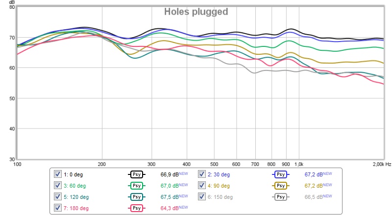
 holes plugged.jpg74.5 KB · Views: 974
 -
 IMAG0507.jpg310.8 KB · Views: 986
Last edited:
Sketch of rear mounted 8" (8FE200) in the enclosure I'm planning:
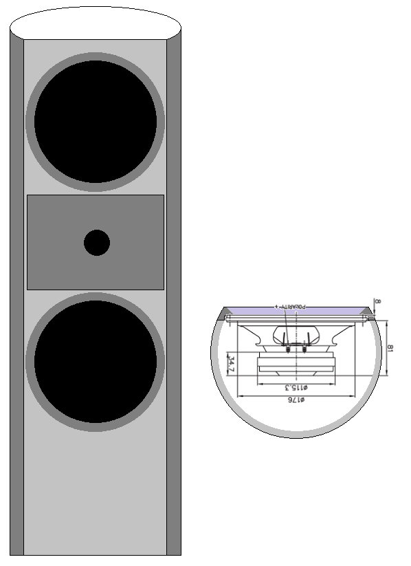
~175 mm ctc for woofer-tweeter. I think I'm going for a 2.5 way to avoid the narrow lobe an MTM configuration gives.
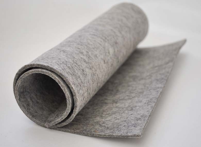
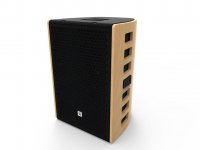
No holes in the sketch, but I don't think I want them visible in the end anyway. Maybe cover the speaker with felt, form and function:
/Anton
~175 mm ctc for woofer-tweeter. I think I'm going for a 2.5 way to avoid the narrow lobe an MTM configuration gives.
No holes in the sketch, but I don't think I want them visible in the end anyway. Maybe cover the speaker with felt, form and function:
/Anton
Attachments

I bought this today:

It's 2x1 m and 7 mm thick and supposed to be used for soundproofing vehicles. Cost: ~20 USD (169 SEK).
I'll try this soon, first idea is to create flow resistance by attaching one layer covering the holes and a large wad in the back of the box to dampen the reflection.
I realize I've kind of flooded this thread with posts, sorry about that. But did you see the results in post #23, the first graph is quite good, no? Why am I not seeing any fall off for low frequencies (except below 150 Hz which is fine anyway)?
/Anton
You might need more/larger holes. I think with my setup right now the area of both slots is a little larger than the driver Sd.
So a total of about 2xSd? What about the length of the holes (thickness of MDF)?You might need more/larger holes. I think with my setup right now the area of both slots is a little larger than the driver Sd.
I'll make more holes as a first step 😊
/Anton
I like this project 🙂
I would be keen to incorporate cardioid midrange in my plan:
www.stereo.net.au/forums/index.php?/topic/89026-exodus-a-beast-of-100db/
I would be keen to incorporate cardioid midrange in my plan:
www.stereo.net.au/forums/index.php?/topic/89026-exodus-a-beast-of-100db/
I bought this today:
View attachment 513034
It's 2x1 m and 7 mm thick and supposed to be used for soundproofing vehicles. Cost: ~20 USD (169 SEK).
I'll try this soon, first idea is to create flow resistance by attaching one layer covering the holes and a large wad in the back of the box to dampen the reflection.
I realize I've kind of flooded this thread with posts, sorry about that. But did you see the results in post #23, the first graph is quite good, no? Why am I not seeing any fall off for low frequencies (except below 150 Hz which is fine anyway)?
/Anton
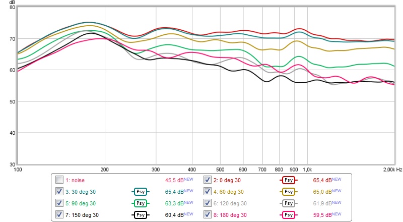
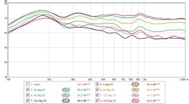
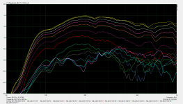
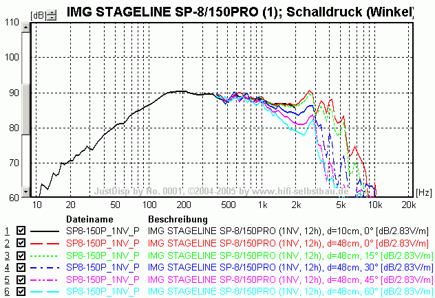
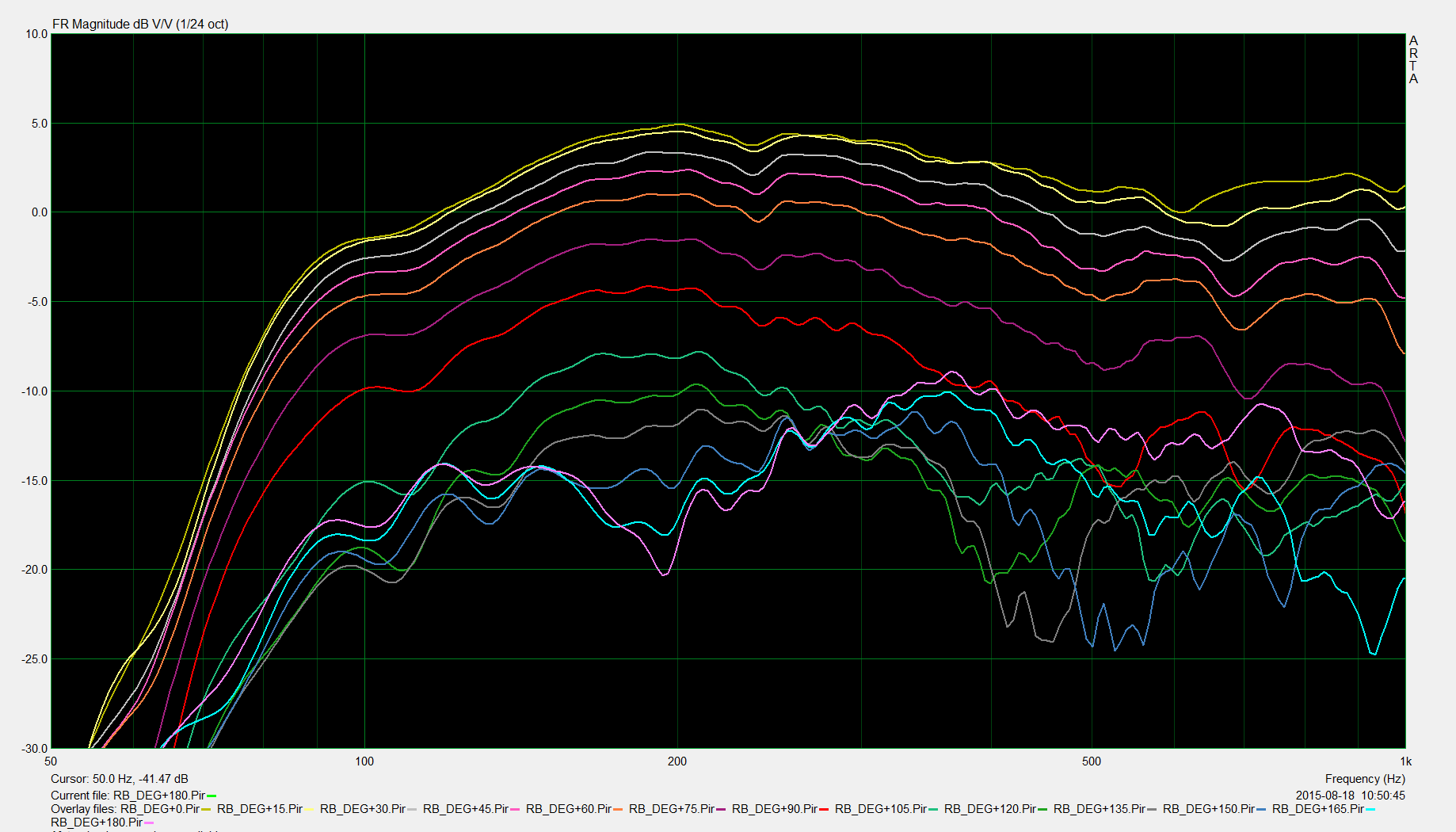
For an idea of what you should aim for, I've added measurements taken during the optimization of one of my most recent passive cardioids. Please note, that for these measurements the microphone was at 3 meters distance and the speaker was rotated around the baffle axis. The directivity therefore looks less high than it does when you move closer to the speaker and you rotate the speaker around an axis closer to the rear of the speaker.
From behind my computer it's very difficult to say what you should do. As I explained before, the end result is always the complex sum of the front-wave and the back-wave. If results are sub-optimal, it is difficult to say which is too loud relative to the other, or which is delayed more.
In your earlier measurements there seems to be a standing wave inside the enclosure, which causes a peak in the response of the back-wave at around 180 hertz. If I understand correctly, the later measurements are with more damping material in the enclosure. Assuming the measurements can be compared one-on-one, the addition of more damping material reduces the standing wave, but it seems to still be there. I'd try more damping material inside the enclosure to further decrease the resonance, but probably you shouldn't restrict air-flow too much. You might be decreasing the level of the back-wave as a whole too much, so I suspect removing the damping material from the holes would improve things.
By the way, with this kind of speaker the measurements at 180 degrees tend to look somewhat less good because the diffraction of the front wave around the baffle is all in-phase there. While optimizing it's probably better to focus on other angles, perhaps 165 degrees.
Attachments
That is really impressive! Do you have a pic to go with that?For an idea of what you should aim for, I've added measurements taken during the optimization of one of my most recent passive cardioids. Please note, that for these measurements the microphone was at 3 meters distance and the speaker was rotated around the baffle axis. The directivity therefore looks less high than it does when you move closer to the speaker and you rotate the speaker around an axis closer to the rear of the speaker.
From behind my computer it's very difficult to say what you should do. As I explained before, the end result is always the complex sum of the front-wave and the back-wave. If results are sub-optimal, it is difficult to say which is too loud relative to the other, or which is delayed more.
In your earlier measurements there seems to be a standing wave inside the enclosure, which causes a peak in the response of the back-wave at around 180 hertz. If I understand correctly, the later measurements are with more damping material in the enclosure. Assuming the measurements can be compared one-on-one, the addition of more damping material reduces the standing wave, but it seems to still be there. I'd try more damping material inside the enclosure to further decrease the resonance, but probably you shouldn't restrict air-flow too much. You might be decreasing the level of the back-wave as a whole too much, so I suspect removing the damping material from the holes would improve things.
By the way, with this kind of speaker the measurements at 180 degrees tend to look somewhat less good because the diffraction of the front wave around the baffle is all in-phase there. While optimizing it's probably better to focus on other angles, perhaps 165 degrees.
I'm not sure about the standing wave theory...
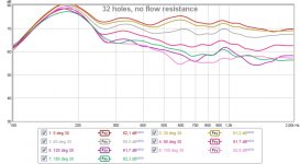
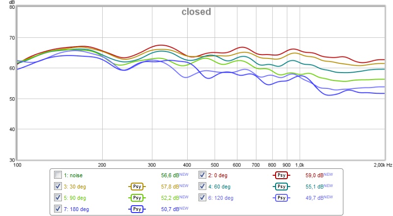
No holes:
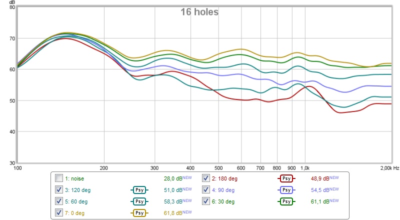
8 holes/side (16*(1.27cm)^2*3.14 = 81 cm^2 ~ 54 % of 2x5" Sd):
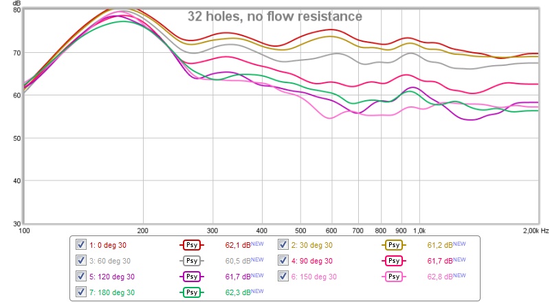
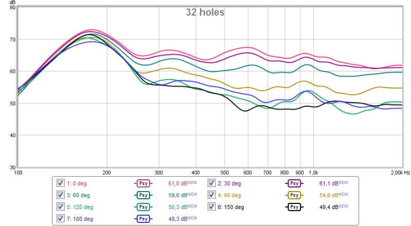
16 holes/side (32*(1.27cm)^2*3.14 = 162 cm^2 ~ 108 % of 2x5" Sd):
All of these where measured with ~1.5 layer of this (6 cm thick):
An externally hosted image should be here but it was not working when we last tested it.
against the back of the speaker. None of it covering the holes.
Then I exchanged for the fiberglass like this:
It's 5 cm thick.
Resulting response:
The hump increases in height and frequency when adding more holes (16->32) which indicates that it behaves like a tuned box (not standing wave). Adding restriction takes the hump down and adds separation between the lines below 200 Hz, but reduces the separation slightly above 300 Hz.
/Anton
Did you guy know about these leaky cardioid systems of kimmosto?
WTC7ex
And his more recent achievements look like this http://kimmosaunisto.net/KS-1807/KS-1807.html#Enclosure
WTC7ex
An externally hosted image should be here but it was not working when we last tested it.
And his more recent achievements look like this http://kimmosaunisto.net/KS-1807/KS-1807.html#Enclosure
An externally hosted image should be here but it was not working when we last tested it.
Last edited:
The hump increases in height and frequency when adding more holes (16->32) which indicates that it behaves like a tuned box (not standing wave). Adding restriction takes the hump down and adds separation between the lines below 200 Hz, but reduces the separation slightly above 300 Hz.
/Anton
You might be right. I do know internal resonances play an important role, but in this case the 'tuned-box-phenomenon' may be the dominant factor. Interesting!
That is really impressive! Do you have a pic to go with that?
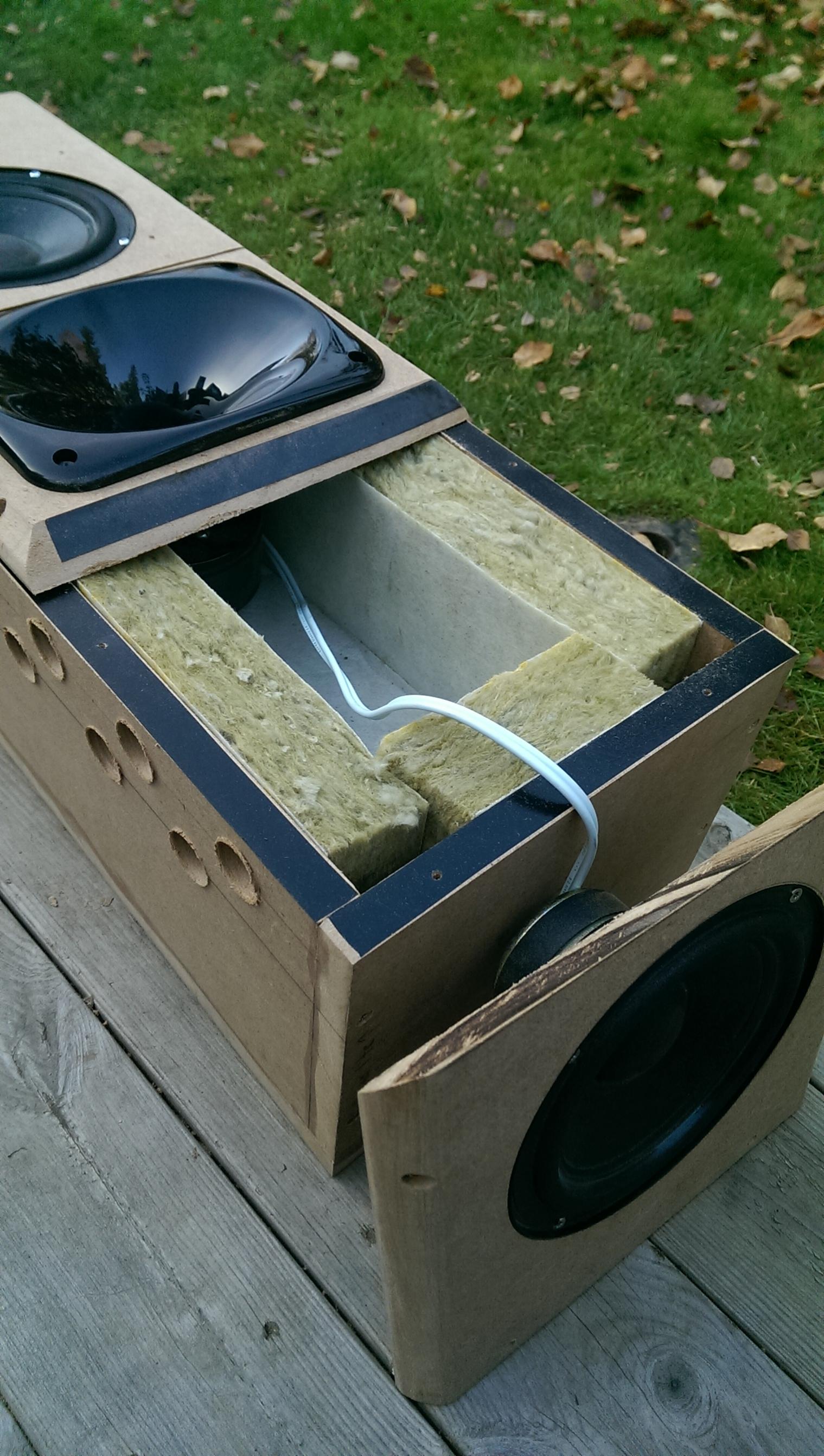
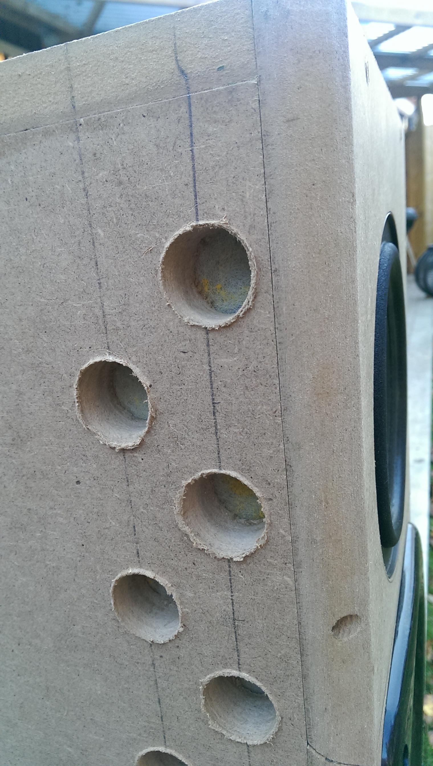
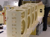
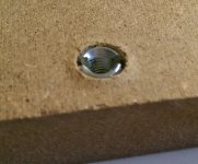
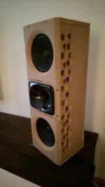
I don't have many images on this computer but these few at least give you an idea of the general construction and the location of the holes. The damping material used inside is polyester fiber.
Attachments
Thanks for the links! They gave me some inspiration.Did you guy know about these leaky cardioid systems of kimmosto?
WTC7ex
An externally hosted image should be here but it was not working when we last tested it.
And his more recent achievements look like this KS-1807ML
An externally hosted image should be here but it was not working when we last tested it.
The polars of the WTC7ex are very impressive! Too bad that the many phase wraps ruins the performance.
Functional and pretty! Is the box ~filled with polyester fiber? Is there something in the vents to act as a flow restriction?You might be right. I do know internal resonances play an important role, but in this case the 'tuned-box-phenomenon' may be the dominant factor. Interesting!
I don't have many images on this computer but these few at least give you an idea of the general construction and the location of the holes. The damping material used inside is polyester fiber.
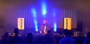
Is that you between the speakers?
My direct reaction now looking at the WTC7ex and your speaker is that maybe I should move the vents back, mine are very close to the front.
/Anton
Experimenting with the holes
I've done two new experiments:
1. Chamfering the holes (12 mm) to reduce the air mass that can vibrate acting as a port (tuned system).
2. Replacing the glass fiber with felt as flow restriction (left the back covered with glass fiber).
3. Added more holes (108 % Sd -> 190 % Sd).
For comparison, here is the response before making any of these changes:
1. Chamfering the holes
I chamfered the holes with a 12 mm router bit:

(Image taken when glass fiber was replaced.)
Resulting response:

No real difference as far as I can tell.
2. Felt as flow restriction
Resulting response:

No real difference as far as I can tell.
3. Added more holes (108 % Sd -> 190 % Sd).
I chose to add the new holes only close to the midbass drivers (not behind the compression driver):

Resulting response:

Some improvement in the low frequency area, now there is about 10 dB of difference (0-180) compared to 6 dB earlier.
Time to decide what 8" to order. The candidates as of now:
Celestion TF-0818
Fs: 95 Hz.
Sensitivity: 95 dB (1 W/1 m)
Monacor SP-8/150PRO
Fs: 56 Hz
Sensitivity: 93 dB (1 W/1 m)
A little to jagged above 2 kHz.
Faital Pro 8Fe200
Fs: 80 Hz
Sensitivity: 95 dB (1 W/1 m)
/Anton
I've done two new experiments:
1. Chamfering the holes (12 mm) to reduce the air mass that can vibrate acting as a port (tuned system).
2. Replacing the glass fiber with felt as flow restriction (left the back covered with glass fiber).
3. Added more holes (108 % Sd -> 190 % Sd).
For comparison, here is the response before making any of these changes:
1. Chamfering the holes
I chamfered the holes with a 12 mm router bit:
(Image taken when glass fiber was replaced.)
Resulting response:
No real difference as far as I can tell.
2. Felt as flow restriction
Resulting response:
No real difference as far as I can tell.
3. Added more holes (108 % Sd -> 190 % Sd).
I chose to add the new holes only close to the midbass drivers (not behind the compression driver):
Resulting response:
Some improvement in the low frequency area, now there is about 10 dB of difference (0-180) compared to 6 dB earlier.
Time to decide what 8" to order. The candidates as of now:
Celestion TF-0818
Fs: 95 Hz.
Sensitivity: 95 dB (1 W/1 m)
An externally hosted image should be here but it was not working when we last tested it.
Monacor SP-8/150PRO
Fs: 56 Hz
Sensitivity: 93 dB (1 W/1 m)
A little to jagged above 2 kHz.
Faital Pro 8Fe200
Fs: 80 Hz
Sensitivity: 95 dB (1 W/1 m)
/Anton


Baffles made for the 8FE200
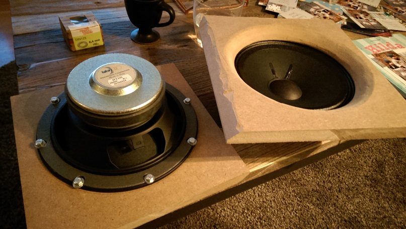
Today I started working on baffles for the 8FE200 so I can use them in my test box.
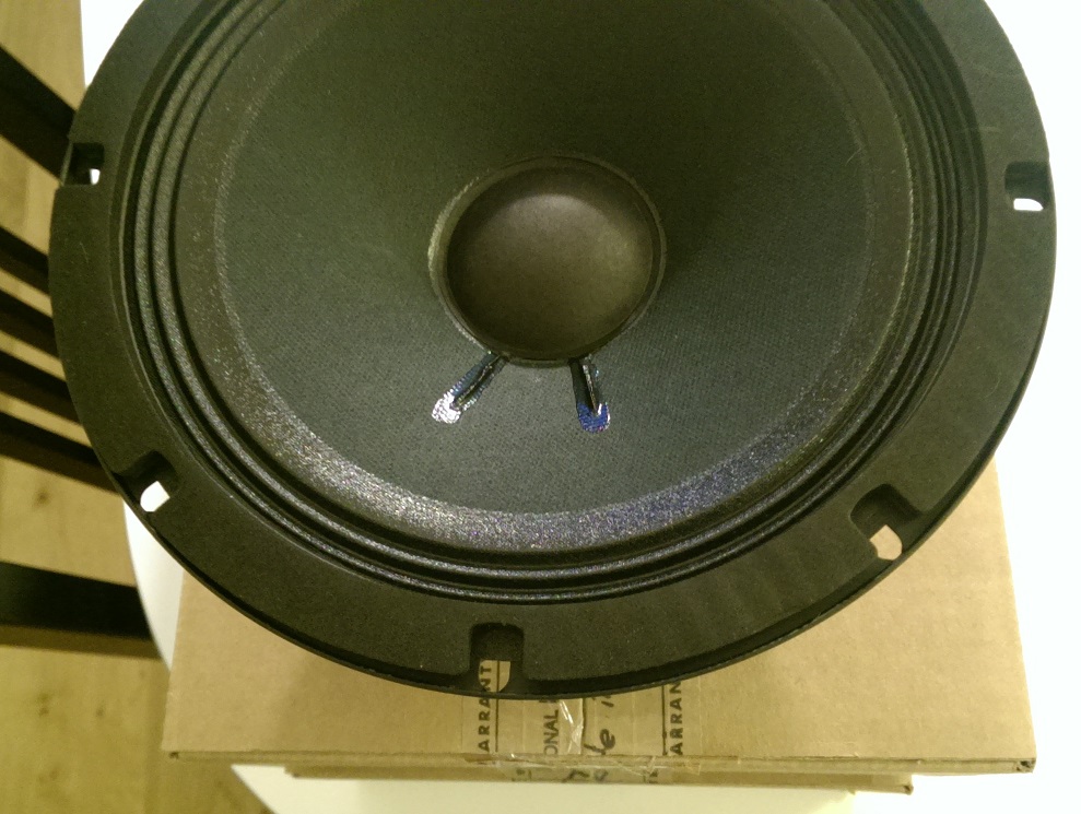
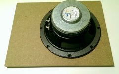
Rear mounted:
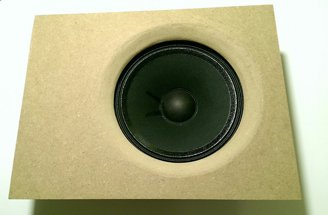
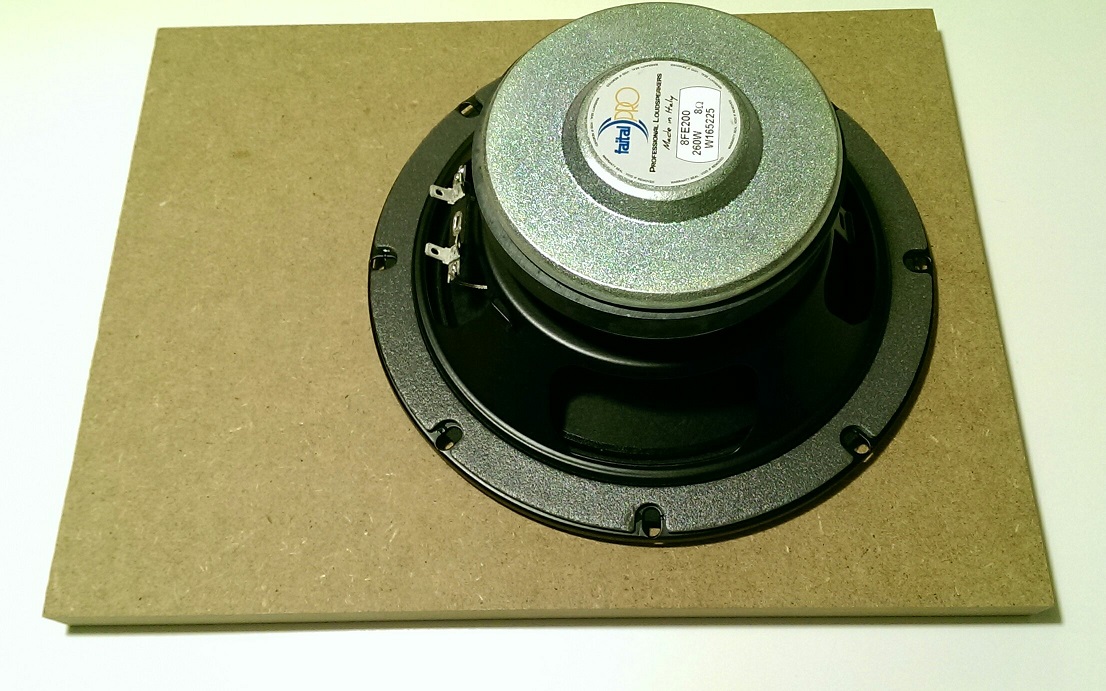
Compared to front mounted:
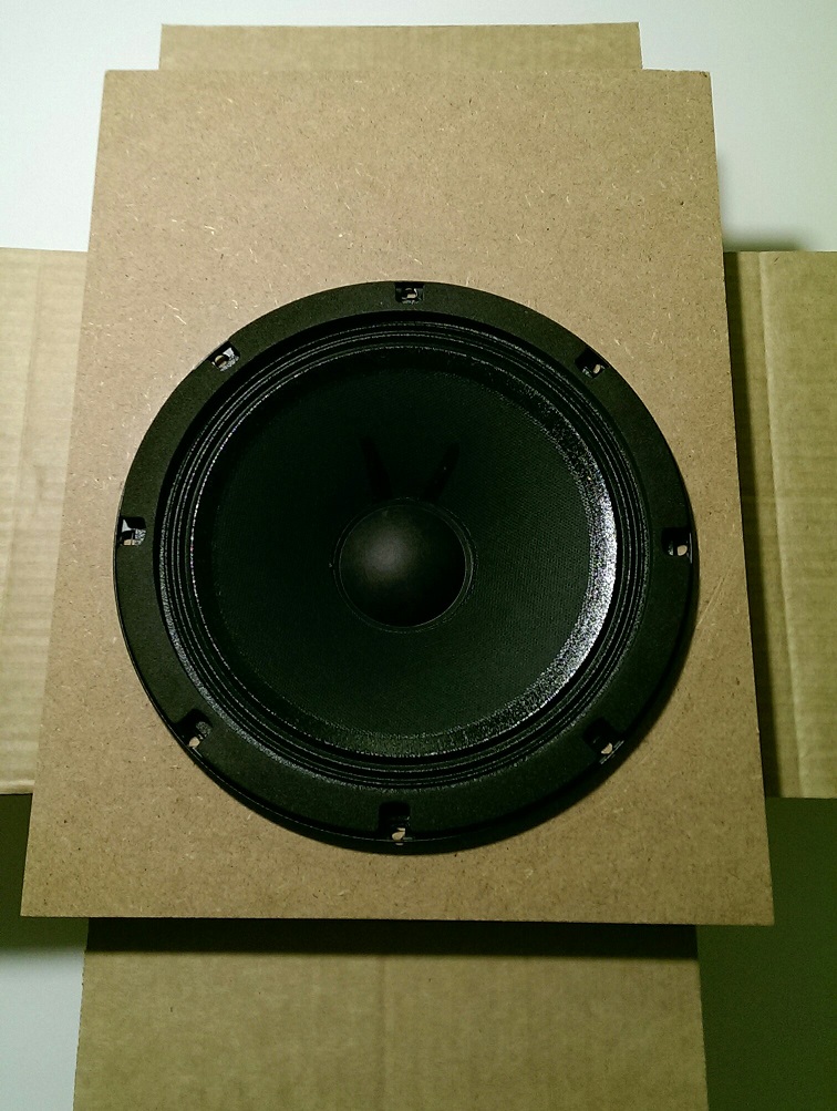
The rear mounting makes them look a lot smaller, which I find is good for WAF.
I'll see if it's possible to make outdoor measurements some day, it's below freezing here and I'm just waiting for the first snow.
/Anton
Today I started working on baffles for the 8FE200 so I can use them in my test box.
Rear mounted:
Compared to front mounted:
The rear mounting makes them look a lot smaller, which I find is good for WAF.
I'll see if it's possible to make outdoor measurements some day, it's below freezing here and I'm just waiting for the first snow.
/Anton
Attachments


A little more work done!
I used these little fellas:

Called "rampamuff" here, best translation I could find is "threaded insert".
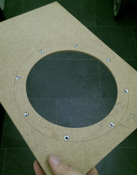
8 inserts.
Both drivers mounted. It was no problem compressing the packer so that the steel basket is in contact with the MDF.
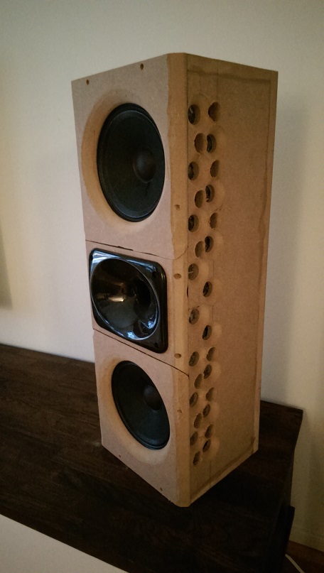
Cables soldered and box closed.

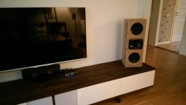
On the media console.
A first measurement:
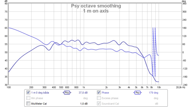
Indoors, on-axis, at 1 m distance, 1.2 m above the floor, 10 ms gating and psychoacoustic smoothing. Mainly to test the high end of the drivers, no serious peaks or dips 🙂
Next step is to make more holes as the holes are currently at 74 % of Sd (56 x 1" holes = 284 cm^2, Sd = 191*2 = 382).
/Anton
I used these little fellas:
Called "rampamuff" here, best translation I could find is "threaded insert".
8 inserts.
Both drivers mounted. It was no problem compressing the packer so that the steel basket is in contact with the MDF.
Cables soldered and box closed.
On the media console.
A first measurement:
Indoors, on-axis, at 1 m distance, 1.2 m above the floor, 10 ms gating and psychoacoustic smoothing. Mainly to test the high end of the drivers, no serious peaks or dips 🙂
Next step is to make more holes as the holes are currently at 74 % of Sd (56 x 1" holes = 284 cm^2, Sd = 191*2 = 382).
/Anton
Attachments


Hi onni, nice project! I'm currently experimenting with gradient type enclosures and believe they have merit too. Sadly I don't have any meaningful/comprehensive measurements (and am far from an expert) but nonetheless have a few questions and thoughts about your project.
What is it about a Supercardiod that you like? Is it the rear nulls that you can aim at the front walls when speakers are toed-in and close to the wall?
I'm not sure if a cardiod/supercardiod woofer and CD waveguide would outperform a monopole woofer and CD waveguide when it comes to having a wider sweet spot. Would be great if they do and am keen to see your results.
From memory, for vent area Kimmo Saunisto recommends 2 x SD but as has been pointed out balancing all the relevant 'cardiod' parameters seems critical to passive cardiod success.
The 'hump' that appears in the lower frequency range of your plots looks like a typical dipole curve (ie first dipole peak). I believe it is pretty common for these type of speakers to transition from cardiod to dipole as they go lower in frequency.
Thank you for sharing your project.
Mark
Looking good, onni!
Hi Mark,
A speaker such as this does not necessarily transition to a dipole at low frequencies. See the example below:
The 'hump' that appears in the lower frequency range of your plots looks like a typical dipole curve (ie first dipole peak). I believe it is pretty common for these type of speakers to transition from cardiod to dipole as they go lower in frequency.
Hi Mark,
A speaker such as this does not necessarily transition to a dipole at low frequencies. See the example below:
- Home
- Loudspeakers
- Multi-Way
- Leaky supercardioid mids