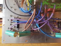
Oh, old Russian resistors (it seems I've seen them with a 1% tolerance too) And a mica capacitor in the input filter .
Nice boards - I hope everything works for you on the first try without any problems!
as far as i've read - the super amp is a little trickier than the standard low tim.
Nice boards - I hope everything works for you on the first try without any problems!
as far as i've read - the super amp is a little trickier than the standard low tim.
Well spotted osscar 🙂 some nice stuff came out of the cold war, I bought a big lot of mics and resistors at a nice price, as to difficulty theres alot of wirring to get connected correct, guess going slow and double check is the way
Attachments

Osscar did you ever get to build that headphone amplifier? The one from that danish hifi magazine?
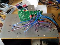
Yes - The boards have been soldered and are working from the first time. I am now in the process of finishing it. I Think there will be 2 inputs and one pre-out. There will also be an LED VU meter.
I am currently waiting the acrylic front panel material from ebay.
I am currently waiting the acrylic front panel material from ebay.
Attachments
What will be your Super amp rail voltage ?
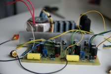
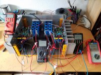
I recently measured my leach amps output power to 8 ohms. For one with + -60V rails and 800vA transformer - approx. 155W before visible clipping in the scope (clean with 0,0x % thd power will be lower without harmonics)
Second one with +-63V and 400VA transformer around 170W .
both have approx. 30,000 uf per rail.
Attachments
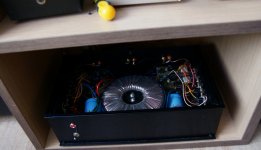

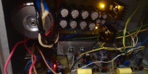
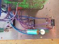
Looking good that head amp, I'm very happy with mine, rails are 70 volt, I dont need all that power, it's a 2 kilowatt toroid with 4 secondary windings, so channel seperation should be top notch.
Just got one channel running, at first it was acting up, using way to much current, then I noticed I forgot the four bias diodes, all good now, 6mv dc offset
Just got one channel running, at first it was acting up, using way to much current, then I noticed I forgot the four bias diodes, all good now, 6mv dc offset
Very nice! For all the work that went into mine, I wish I built the Super Leach. I want more power. hahaha
With modern output transistors like the MJL4281 you *can* run the original Leach on higher voltages normally associated with the SuperLeach. Use 5 or 6 output pars and you’re golden. Even the 15024 is good enough - they didn’t have the PNP version back when Leach designed these, and even getting them when they first came out was too much for poor college kids. So he designed it to make use low lower rated parts - and you end up with the stacked output stage. 200 volt front end transistors that are low noise are no problem these days either, so you don’t have to resort to the cascode.
The s-Leach topology works perfectly fine with power supply voltages of +/-130 volts, with enough modern outputs in parallel of course. I used to use those to drive Labhorns.
The s-Leach topology works perfectly fine with power supply voltages of +/-130 volts, with enough modern outputs in parallel of course. I used to use those to drive Labhorns.
Granted it's outdated by superior components, many have pointed that out, but I wanted the real deal, as dr leach designed, my goal is a sweet sounding amp, I dont care about the 0.001 distortions, my speakers make sure of that.
Its nostalgia!
Its nostalgia!
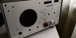
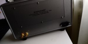
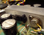
A question, I've assembled one channel and the rail power goes to output devices through a 3mm screw to collector, I stumbled across this photo of a commercial amp, is this a better method ? I'm not a fan of powering through screws.
Is it only theoretical or could I gain anything by soldering directly to cans???
Is it only theoretical or could I gain anything by soldering directly to cans???
Attachments
Last edited:
Granted it's outdated by superior components, many have pointed that out, but I wanted the real deal, as dr leach designed, my goal is a sweet sounding amp, I dont care about the 0.001 distortions, my speakers make sure of that.
Its nostalgia!
If you wanted to build it “exactly as Dr. Leach designed”, you are limited to power supplies of around +/-55 volts. 65 if you add another output pair or two, but then you’re SOL until you start changing components. If you wanted to run the same circuit (the non-super) on +/-85 volts “because you want more power” you could use 5 MJ15024/5 or MJL4281/4302 in parallel. It would then be somewhere between an Original Leach Amp and a CS800. You couldn’t just do that back then but you can NOW.
I don’t consider changing output transistor types, bumping the supply voltage, or both to be really a fundamental change in the design.
A question, I've assembled one channel and the rail power goes to output devices through a 3mm screw to collector, I stumbled across this photo of a commercial amp, is this a better method ? I'm not a fan of powering through screws.
Is it only theoretical or could I gain anything by soldering directly to cans???
I’ve always been leery of soldering directly to a can. Solder won’t always stick properly - and you have to get it hotter than the blazes of Hell and Damnation to do it. Back in the days of the aluminum TO-3 you couldn’t do it at all. If you don’t want to run through the screw, you can put a soldered or properly crimped ring terminal under the screw on the top side. The terminal then contacts the case directly.
I also don't trust the wires soldered to the case ...i think the screw provides good contact in terms of pressure and area(if compared to rail fuses for example)
Good progress - the finishing of amp is not far off!
for standard low tim I use the recommended 50mA per transistor (D.Self recommends 74mA at 0.33Re). Given that I have 60V rails for one and 63V for the other, the heat-sinks are also a bit warm at 50mA.
Dr. Leach suggestion:
I recommend setting the voltage across Q7, i.e. the voltage between the collectors of Q22 and Q23, so that that amplifier is biased at 120 mA. This will give the same quiescent power dissipation per heat sink as in the Low TIM Amplifier.
i would stick to this ... and then adjust depending on the temperature / FFT etc.
I also don't trust the wires soldered to the case ...i think the screw provides good contact in terms of pressure and area(if compared to rail fuses for example)
Likewise, I use a crimp connection with a good quality crimp tool and then solder down into the crimp/cable hole. Use a stainless steel 'crinkle' washer between the transistor case and the crimp and it bites into the metal to form a good electrical connection.
Regards
Mike
- Home
- Amplifiers
- Solid State
- Leach's Low TIM amplifier