Hi guys,
I have read this thread with great interest. You talk about over- and under-compensation.
But what is in your opinion the optimal figure, per degree C measured in mV over one of the emitter resistors?
I have read this thread with great interest. You talk about over- and under-compensation.
But what is in your opinion the optimal figure, per degree C measured in mV over one of the emitter resistors?
revintage said:Hi guys,
I have read this thread with great interest. You talk about over- and under-compensation.
But what is in your opinion the optimal figure, per degree C measured in mV over one of the emitter resistors?
0mV/C, but this is impossible!

Ha,ha,ha!
Allready knew that answer. Please come back to Leachamp reality!
Let´s change optimal to practical. My guess is somewhere between -0,1mV/C to -0,5mV/C.
Allready knew that answer. Please come back to Leachamp reality!
Let´s change optimal to practical. My guess is somewhere between -0,1mV/C to -0,5mV/C.
Hi,
The generally recommended range of Vre on the output transistors is 15mV to 25mV to maintain optimum ClassAB bias.
If this were rigorously applied for all operating conditions, from warm up through low temperature use through to cooling down after hard use then simply applying that 10mV range over 60Cdegree requires 0.17mV/C.
I quite like the idea of slight over compensation to automatically reduce bias as temperature rises so that gives us Tcomp<= -0.17mV/C. However for quiescent range testing I would half that requirement to -<0.1mV/C and the little bit of spare we have, try to keep within that 15mV to 25mV even for transient junction temperatures that heat monitoring can never exactly follow.
Any other thoughts?
revintage said:Ha,ha,ha!
Allready knew that answer. Please come back to Leachamp reality!
Let´s change optimal to practical. My guess is somewhere between -0,1mV/C to -0,5mV/C.
You will never achieve that with high dynamic signal transients and without temperature sensing device in close proximity with power die. The key is ThermalTrack technology or something similar.
roender said:
You will never achieve that with high dynamic signal transients and without temperature sensing device in close proximity with power die. The key is ThermalTrack technology or something similar.
 , the thread is about ThermalTrak isn´t it?
We where discussing ThermalTrak in the Leach amp. I asked about over or under compensation referreing to that. So I recconed ThermalTrak was already thought for. Nothing to get upset about 😉 .
revintage said:We where discussing ThermalTrak in the Leach amp. I asked about over or under compensation referreing to that. So I recconed ThermalTrak was already thought for. Nothing to get upset about 😉 .
Lars,
Please give us your opinion about class B thermal compensation using ThematTrack devices and I'll see if I have someting to add.
Thank you,
Mihai
Hi Mihai,
Sorry if you thought I was unfriendly! You must have misunderstood it all. You made a joke of my initial question and I joked back.
I had no opinion, because of that I made the question(with temp comp and ThermalTrak in mind):
"But what is in your opinion the optimal figure, per degree C measured in mV over one of the emitter resistors?" After your first answer I changed "optimal" to "practical".
As 0mV/C, as you say, is impossible there must be some figures below that that could be recommended.
I got an answer from AndrewT that gave me some insight but hopefully you can view it from some other angle to make it even more clear.
Brgds
Lars
Lars,
It wasn't a joke, the best TC is zero mV/C.
We have two "problems" to solve with TT devices, first, thermal behavior difference between transistor and MUR120 inside diode and second, lack of thermal sensing device inside driver transistor. Power transistor have TC = -2.1 ... -2.2 mV/C and the inside diode has TC = -1.6 ... -1.7mV/C ( see Bob Cordell and Charles Hansen comments in this thread http://www.diyaudio.com/forums/showthread.php?postid=1282579#post1282579 )
The simple way in solving this problem is to use a number of NJL (MUR120) diodes which give us as close as possible total TC to total TC of series forward BE junctions in output stage and to thermally couple drivers with output devices.
The "perfect" approach is to use a microcontroller but it is overkill and not a good sounding solution.
Cheers,
Mihai
I always prefer the simplest approach:
http://www.diyaudio.com/forums/showthread.php?s=&threadid=111756
http://www.diyaudio.com/forums/showthread.php?s=&threadid=111756
Attachments
Hi again Mihai,
Would you mind mailing me the ltspice-file of your RMI-FC100? Think I would learn a lot by simming your circuit. Have also just ordered 5 samples of each njl0281 and njl0302 from OnSemi to find out how they act IRL.
Would you mind mailing me the ltspice-file of your RMI-FC100? Think I would learn a lot by simming your circuit. Have also just ordered 5 samples of each njl0281 and njl0302 from OnSemi to find out how they act IRL.
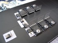
zerohead_ak47 said:leach vs thermal trak output devices
Hi zerohead,
very nice - and you can show board?
Is this thread dead? I have been waiting for someone to demonstrate using ThermalTrak devices in a Leach amplifier.
Is this thread dead? I have been waiting for someone to demonstrate using ThermalTrak devices in a Leach amplifier.
I was hoping to do just that experiment myself using BrianGT's Leach amp board, but I only got the one prototype board to build up. I used regular NJL21193/94s in the chassis just to verify stable operation, but lacking a second channel and any response from Brian about more boards, I've left the project to gather dust for now.
At some point I will reinstall with the ThermalTrak devices (some creative lead-bending and rewiring required) and see how the bias behaves--and whether these faster transistors are stable in the circuit! This chassis doesn't have as much heatsinking as I'd like--and I like to push the bias for minimum possible distortion--so reliable thermal tracking is of more importance now.
And if I could just interest Brian in building more of those boards...
Keep prodding me, eh?
Mod done, now puzzling over the results. Two diode drops weren't enough to bias the amplifier correctly, as expected, so a couple of 1N4004s were added to make up the difference (and base stopper resistors were removed as an afterthought). I can get distortion down under .005% by overbiasing but the heat dissipation is excessive on this chassis. Any thoughts? Too much reading to do on Vbe multipliers...
Distortion goes up rapidly with frequency, so I'm going to have to look at that aspect of the design, too.
Distortion goes up rapidly with frequency, so I'm going to have to look at that aspect of the design, too.
Damon,
Do you have access to Bob Cordell's book? He has some excellent advice and observations on the subject in there. I need to set aside some time to digest it myself.
Do you have access to Bob Cordell's book? He has some excellent advice and observations on the subject in there. I need to set aside some time to digest it myself.
Indeed, that book has been my 'bible', but it's tough to absorb. At a start, I may have to hack the Vbe multiplier.
- Home
- Amplifiers
- Solid State
- Leach To Thermal Trak