Power Supply Components
The power supply circuit diagram is the same as for the Low TIM Amplifier. The parts are the same with the following exceptions.
* T1 - The transformer should have either a center tapped secondary or two separate secondary windings which can be wired in series. With 120 V ac rms applied to the primary, the no load secondary voltage should be 120 to 130 V ac rms for a center tapped secondary or 60+60 (60x2) to 65+65 (65x2) V ac rms for two secondary windings. This should give a no load amplifier power supply voltage of plus and minus 85 to 93 V dc. Some transformers are rated at 115 V ac rms on the primary. With 120 V ac rms applied, the secondary voltage will be greater by a factor 120/115. If the transformer is rated at full load, its no load voltage will be 15% to 20% higher. I would recommend a transformer current rating of at least 6 A.
jacco vermeulen said:Number one.
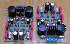
Regulation circuit for the Mark Levinson 23.5
I've buit that regulator and was using them in A-75 front end. Still have the pictured boards, if someone is interested, they are for sale.
Attachments
Member
Joined 2002
I'm selling complete boards, $50 a board.
They can be adjusted for wide range of voltages, the ones in picture are set to 50V DC.
They can be adjusted for wide range of voltages, the ones in picture are set to 50V DC.
Peter, you are an audio designer.
What is your opinion on the ML active regulation ?
In the A75, that means not the original voltage doubler circuit of the A75 ?
What is your opinion on the ML active regulation ?
In the A75, that means not the original voltage doubler circuit of the A75 ?
Member
Joined 2002
Peter Daniel said:I'm selling complete boards, $50 a board.
They can be adjusted for wide range of voltages, the ones in picture are set to 50V DC.
Please email me so we can talk : O ) about this board.
jacco vermeulen said:Peter, you are an audio designer.
What is your opinion on the ML active regulation ?
In the A75, that means not the original voltage doubler circuit of the A75 ?
I didn't realy compare this reg to any other, so it's hard for me to comment. However, A-75 sounded really good, may be in part due to those boards? 😉
I was never using a voltage doubler, and I've built 3 sets of those amps.
True, the boards look great
(as did the other from you i have seen till now)
The end of the board resembles the GC again
(as did the other from you i have seen till now)
The end of the board resembles the GC again
The thread has cooled down a bit. Mikett has photocopied and sent me the Boak Regulator (with Walt Jung’s modifications) documentation. It seems like a nice regulator, especially considering the date when it was designed (much like the leach amp). I was surprised that it’s a two stage design(two regulators the output of one is the input of the other).
I believe that the rules of DIY audio don’t allow me to post it even if I could. I am in the process of redrawing it in pdf format (maybe I can post that).
The semiconductors seem to be still available. However they are somewhat old I was hoping someone could recommend some modern day improved parts. What would be really great is if I could get way with using some of the same parts Jens leach amp uses, as this cuts down my parts list.
The parts I am looking to replace are:
1N5401
MJE2955
MJE3055
TIP35C
TIP36C
TIP31C
TIP32C
LM340T5
LM320T5
Leve
I don't recall sending you photocopies of the reg but if you have them, great.
There are really three key modules there, a Preregulator/capacitance multiplier, the three terminal current split with the 2955 and the lifting of the ground reference for the three terminal device. I have always used ( MJ802/4502) for the pass transistors and had good results. The MJ 15003 did not seem to have as high a peak current capability as the 802/4502. The voltage on the pass elements are not that high.
Again, I'm sure that there are improved three terminal regs such as the LT series from Linear. Also there might be better outputs than the MJ802/4502 I used 20 years ago. Make sure you use the modified regulator as per Walt Jung suggestions.
You can tell that this reg is optimized for the low and midrange performance. The HF area is left to output caps to flatten.
Still, has anybody built a high voltage low current reg for a power amp front end with the bandwidth of Walt Jung/ Jan Didden super regulator?
The improvement in a "line stage" is obvious with that PS, imagine it's effect on something with 20-26 dB of gain!
I’m sorry I got you confused with somebody else. If the Jung type opamp based regulators are better then these boosted designs, there are “power op-amps” that could be used to make such a regulator. OPA541 can run off of rails of +-40V and can output 5A. This would be more then sufficient to drive the base of a power transistor in a Jung type topology. Does anyone have any thoughts on this?
Leve
Leve
This is where I stand. I am going to try a regulator, it’s just a question of which one. The Boak Regulator is currently looking like the best one. It’s performance is not outstanding but it’s pretty good and it has been tested in many amps and is known to work well and it’s one of only two or three that will work at these currents and voltages.
However I know if someone wanted to they could design a better regulator then the Boak Regulator. In 20 years there have emerged better parts that are faster and capable of withstanding more voltage. The Jung regulator seems simple I have looked at it, however I don’t think I have the skill to upgrade it to the current and voltage where talking about.
If some new ideas come along that makes it possible to reliably build a better regulator I’ll obviously go down that path instead of the Boak. However, at the current time there are no better regulators so it looks as if the Broak is still my best bet.
just a quick word of caution here... I have tried many types of regulator over the years, both published designs and high voltage /high current designs of my own, and whilst I am aware that the levinson amps and also the Naim amps use full regulation with success, the majority of attempts to fully regulate will result in worse sound than with a large unregulated supply (usually sounds more "grey", "leaden", "solid-state" and undynamic than unregulated version), regulation of input/driver stages is usually more successfull but any improvement is dependent on the PSRR of these stages.
I have a feeling that there will be replies to this saying that this is not your experiance of regulated amps and that they DO sound great but this is not what I have found..... dont say I did'nt warn you
This is one topic in which I find myself in complete agreement with a certain D.Self
I have a feeling that there will be replies to this saying that this is not your experiance of regulated amps and that they DO sound great but this is not what I have found..... dont say I did'nt warn you
This is one topic in which I find myself in complete agreement with a certain D.Self
Peter Daniel said:
I've buit that regulator and was using them in A-75 front end. Still have the pictured boards, if someone is interested, they are for sale.
Pretty good regulator, I should say...

Is it somehow possible to get your board layout/schematic (if it's not also for sale)? My amp just happens to require 50 Volts 🙄
Look what I found. Some interesting PS for front ends. Also looks like PCBs are available
http://home.kimo.com.tw/ucccap/
http://homelf.kimo.com.tw/ucccap/pics/HV01.jpg
http://home.kimo.com.tw/ucccap/
http://homelf.kimo.com.tw/ucccap/pics/HV01.jpg
Well, the information there might be pretty useful, but it's written in hieroglyphs. And furthermore, there are some parts not available in any shop nearby. So, I've decided to buy the SPS for my headamp from a local enthusiast.
But I have an another question: is the Jung Super Regulator (the latest version) capable of driving a 50V-load @ 4-5 Amperes? The thing is that the regulator from my 2*150W amplifier had burnt a few days ago, but the amp itself and the transformer are still alive. I tried to find a replacement for the zeners and the power transisors, but they are obsolete and very hard-to-find (GDR-made).
Also I tried to use passive filters (two large 0.01 F capacitors), but it doesn't seem to sound very good.
Any help would be appreciated.
The Jung Super Reg is not capable of that kind of current, think about less than one tenth that.
Using the second link I provided it appears that circuit provides a general idea of how to scale up the Jung Super Reg for high voltages.
Anyone have any further comments on how to get the Jung Super Reg for high voltages?
Using the second link I provided it appears that circuit provides a general idea of how to scale up the Jung Super Reg for high voltages.
Anyone have any further comments on how to get the Jung Super Reg for high voltages?
To get higher voltage it should be just a matter of adding a x2 gain level translator stage between the output of the op-amp and the series pass device. The op-amp continues to run from the same voltage as now but the level translator and pass device run from the higher rail voltage. The new stage would have to be fast and should be run at an appreciable current, also it would be phase inverting and so the = & - connections to the op-amp would need to be reversed.
Another method is to replace the op-amp IC with a discrete op-amp built to take the voltage. In both cases the compensation would need some playing with.
Another method is to replace the op-amp IC with a discrete op-amp built to take the voltage. In both cases the compensation would need some playing with.
Mikett said:Anyone have any further comments on how to get the Jung Super Reg for high voltages?
I was playing around with this a while back but haven't built it.
- Status
- Not open for further replies.
- Home
- Amplifiers
- Power Supplies
- Leach Super Amp Regulated supply