Jung's superregulator in stock form has a maximum output
voltage of 24 volts. I think it would take fundamental
redesign to adapt it for significantly higher voltages.
I'd consider voltage regulation for the pre-driver stages,
or even the driver, but as an outboard solution that could
be wired in separately. It probably would not be difficult
to use a good three-terminal regulator in place of the
existing dropping resistors; I've thought about that for
years but just haven't followed up on it. I'm sure it could
be 'floated' on top of an existing board as there are
only about five or so parts involved, per rail.
Full regulation of the output stages is a lot more ambitious,
equivalent to doubling the complexity of the amplifier, and
adding significantly to dissipation.
I'd have to hear the results to go to that extent in building
a power supply, and would rather go with a switching
supply at any rate.
Has anyone tried this?
This circuit, with normal small signal opamps and proper part values, is able to provide regulated voltage of more than +/-100V
This circuit, with normal small signal opamps and proper part values, is able to provide regulated voltage of more than +/-100V
An externally hosted image should be here but it was not working when we last tested it.
I'm not an EE but if in the simplest fashion, if you float the grounds of each rail with a zener, you can lift the volatge up on each side. If higher currents are seen, then a "power zener" with a pass transistor can be implemented. Of course this can be refined by using better voltage references but the lifting concept is valid.
Terry,
To answer your question, in essence yes, most of these can be built out to drop 125v to 90v. The pass transistor, be it BJT or mosfet only has to deal with the potential difference from the highest possible voltage in to the lowest defined output, in this case 35volts. Personally I'd use pass transistors that can deal with the full load voltage of the supply, but it isn't strictly necessary.
But, and as usual it's a big but, if you expect, say 5 amps of output from this bad boy you are immediately sent into the big transistor and heatsink department of the local supermarket. 35v at 5amps is 175watts...of course on average it will probably only be half this, but then again you have 2 regulated rails.
The only one of these schematics explicitly designed to be used in the context of a high current, big output class AB amp of the leach type is the Ryan regulator. It was created to sit in the case of the Adcom 555, mark I. He successfully used the original heatsinks, because the nature of the pass transistors power dissipation is to be the inverse of the output transistors.The total amount of power dissipated is increased, but not by much, and of course the overall dissipation of the output stage proper is lowered.
Ryan chose to use some very good output transistors from sanken, fast enough to keep up, and robust enough to deliver the current the amp could deliver. Arguably the sanken transistors are better than the ones used in the output stage of the 555. I've made a couple of single output versions of these and put them in the Adcom 545ii, with very noticeable improvements, so I know it works. I have the ryan article somewhere, if I can find it I'll scan it and put it somewhere for you guys to look at. IIRC it lowered PSU ripple and droop from a few volts to a couple of tens of millivolts, not bad for a 20amp regulator.
It's kind of like you are cascoding the entire amplifier...and as such the regulator has to have the same attention to detail and at least in current has to match the overall capabilities and expectations of the amp itself. No good making a 5 amp regulator for an amp that can drop 15amps into a reactive load...
Hope that helps
Stuart
actually
...Ryan used some transistors that are no longer available, but the recommended replacements from Sanken - 2sa1216/2sc2922 are very nice.
Stuart
...Ryan used some transistors that are no longer available, but the recommended replacements from Sanken - 2sa1216/2sc2922 are very nice.
Stuart
Member
Joined 2002
http://www.audioxpress.com/bksprods/pcbs/nelsonpass.htm
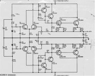
ITEM # PCBP-10B Pass/Thagard A75 Power Amplifier
From Audio Amateur Issues 4/92 and 1/93. Pass/Thagard A75 2-channel power amplifier power supply board. 3-3/8 " x 5". 1 lb. $8.95
The Ryan regulator has some problems as published. Holton has a fix published.
http://home.kimo.com.tw/skychutw/
Then click through to 'ampzilla', 'son of ampzilla'
Hafler does the same on the XL280, XL600
djk said:http://www.audioxpress.com/bksprods/pcbs/nelsonpass.htm
ITEM # PCBP-10B Pass/Thagard A75 Power Amplifier
From Audio Amateur Issues 4/92 and 1/93. Pass/Thagard A75 2-channel power amplifier power supply board. 3-3/8 " x 5". 1 lb. $8.95
Does this provide any regulation DJK?
"Does this provide any regulation DJK?"
Yes, it uses MPSA42/92 and MJE13031/30 pairs
http://www.passdiy.com/pdf/a75p2.pdf
If more than 150V total is needed then use the MJE15032/33.
Board has other goodies (all optional) on it too, inrush limiter, fan speed regulator, etc.
Yes, it uses MPSA42/92 and MJE13031/30 pairs
http://www.passdiy.com/pdf/a75p2.pdf
If more than 150V total is needed then use the MJE15032/33.
Board has other goodies (all optional) on it too, inrush limiter, fan speed regulator, etc.
not for the output stage
The regulator you mention is not for the outputs, it doesn't have anywhere near the capacity for that, but it would be perfect for everything else...
Stuart
The regulator you mention is not for the outputs, it doesn't have anywhere near the capacity for that, but it would be perfect for everything else...
Stuart
Hi guys,
Please excuse my ignorance, but the Superamp is designed to run on 90V rails. So far, almost all of the regulated supplies that folks have listed are not rated for anywhere near those voltages. Since this thread was birthed out of the Leach Superamp thread, shouldn't we be striving to come up with a regulated supply that will serve that amps needs?
If you have a design that can be modified to supply those voltages, would it be too much trouble to show how it should be modified to meet that purpose?
Thanks, Terry
it appears we are all stack here. It appears difficult to create an all out regulated PSU at such voltages with the added bonus that you would need this to output 5 A or so as well.
The more knowledgeable members should shed some light in this path, to us mere mortals.
The more knowledgeable members should shed some light in this path, to us mere mortals.
Hi Terry,
it looks as if two conversations are talking place on this thread.
One is about an active voltage regulator for the front end of the Super Leach.
The second for obtaining regulated powerlines for the output stage.
The first one is not difficult.
It needs few components, a regular Joe like a BD139 or BD140 is fast and big enough to deliver the current required.
Active regulators need very fast, wide band, devices for adequate regulation.
Devices like the 139/140 go way over 100 mHZ bandwidth, a couple of 100 mA they deliver easily with a decent heatsink, say 10 C/W.
An active regulation for the output stage needs big heatsinks, high power transistors, multiple ones.
And they need speed too, and that costs !
The posted regulator from walkabout Anthony Holton delivers plenty amps for such an output stage.
Problem is that i am one of the few that have the 2SC2565 and 2SA1095, Toshiba stopped production.
Replacements like a 2SA1303/2SC3284 can be used, they are not as fast as the ones in the circuit, bandwidth is much lower , at 50 MHz.
A single one probably costs as much as several IRFP240's in the US, the Leach requires a substantial number of them.
Heatsinks will be big, cost a lot of money, and you'll need a big chassis for them.
With class A output stages, an active regulator for the output stage makes a lot of sense.
The regulator can drop noise level due to the high bias enormously, and as mentioned you're talking a constant current source with class A amps.
Regulation for class AB output stages is questionable, i think.
The current at constant voltage changes from 100 mA to way over 10 amps if needed.
I have built a couple of class A amplifiers with full regulation.
With a fully regulated output stage the obvious, in my reasoning, would be to transfer the Super Leach to a high class A or full class A amplifier.
Given the power level, i'll settle for class AB.
That is why i am building the Leach, Pass doesnt do AB's.
For the front end i mentioned one earlier that can be changed for 90 volts operation. If needed i can deliver ten circuits that do the job.
Who knows, maybe Master of the Universe Self made a couple.
For the output stage i can get you one too that does 90 volts in, 75 to 85 volts out, delivering 10 to 20 amps.
But tiny question, do you want it ?
There may be an alternative.
Norman Thagard designed and built an amplifier in the 90s, with advice from Nelson Pass.
The output stage used a combination of MJ150** BJT's and Mosfets. Mr astronaut called it Bi-Mos.
It is not the same as full active regulation, somewhere in between.
The output stage looks like the Double Barrel, both devices are stacked.
But the Base and Gate of the BJT and Mosfet are not connected, one handled the current, the other the voltage.
"If you have a design that can be modified to supply those voltages, would it be too much trouble to show how it should be modified to meet that purpose?"
If you can't do it from the instructions provided, maybe...
This is DIYaudio.com last time I checked.
Go to the Leach site and figure out the bias currents from the instructions provided (5th grade math required).
Plug that number into the (5th grade math required) instructions at the PassA75 site.
If you can't do it from the instructions provided, maybe...
This is DIYaudio.com last time I checked.
Go to the Leach site and figure out the bias currents from the instructions provided (5th grade math required).
Plug that number into the (5th grade math required) instructions at the PassA75 site.
Regarding the use of regulators with power amps, the choice of running only low-power circuitry from the regulator and high-power circuitry from an unregulated supply is not nearly as big of a compromise as it might seem at first.
If you conceptually split the power amp into input stage / VAS combo in one half, and output stage on the other half (including all 3 stages of emitter followers in the Leach amp case), analysis of the circuit shows that the input stage / VAS combo dominates the power supply rejection performance. The power supply rejection of emitter followers is actually quite good compared to a typical input stage / VAS combo. This is a good thing, because it says if you run the input stage / VAS combo on a regulated supply and the output stage from the unregulated supply, you have the possibility of dramatically improving the overall PSRR of the amp (if the regulator line regulation is mathematically considered part of the amp itself). The current demands of a regulator designed to do this become quite reasonable, and there are no efficiency issues like you'd see if you tried to run the output stage from a "monster regulator". This means "garden variety" regulators can be used, with the necessary mods for high-voltrage use.
Below are links to a couple of alternatives for adapting the LM317/337 to high-voltage use. In the Linear Tech app not below, the relevant circuit is in Figure 11 and described in the text nearby.
http://www.linear.com/pc/downloadDocument.do?navId=H0,C3,P1243,D4099
The National app note below describes a similar circuit:
http://www.national.com/an/LB/LB-47.pdf
Hope this helps,
Andy
- Status
- Not open for further replies.
- Home
- Amplifiers
- Power Supplies
- Leach Super Amp Regulated supply