Help......!
Hio Guys,
I found the DIY Audio Wiki on: http://www.diyaudio.com/wiki/index.php?page=Leach+superamp+board+possible+group+buy
As I understand this Project is not "100% Clear"?
So, there is no finished layout and the Wiki is only a "wishlist"?
I am very interested in this Leach Amp PCB Group Buy and hope
it will reach the final GB stage.
Thanks in advance and regards
Ayhan
(Germany)
Roland, Do you think you could get some boards made from that layout. There are quite a few people who would like some. Tad
Hi Tad,
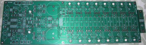
The size is 4.3x13.25 - fits the $33 per piece.
Looking torward to order prototypes from advanced (www.4pcb.com) in the next couple of weeks.
I couldn't attach top and bottom side here due to space constraints. I can send you gerber files if you want.
regards,
Roland
The size is 4.3x13.25 - fits the $33 per piece.
Looking torward to order prototypes from advanced (www.4pcb.com) in the next couple of weeks.
I couldn't attach top and bottom side here due to space constraints. I can send you gerber files if you want.
regards,
Roland
rolland,
greetings.
Great looking pcb.
if you don't mind, can you send the pdf file to my email address dexter@telkom.net
many thans in advance.
best rgds,
greetings.
Great looking pcb.
if you don't mind, can you send the pdf file to my email address dexter@telkom.net
many thans in advance.
best rgds,
rolandong said:Hi Tad,
The size is 4.3x13.25 - fits the $33 per piece.
Looking torward to order prototypes from advanced (www.4pcb.com) in the next couple of weeks.
I couldn't attach top and bottom side here due to space constraints. I can send you gerber files if you want.
regards,
Roland
hi roland,
can you get me 4 boards?
Leach Rebuild X8
I've built 6 of the LOWTIM amps and two of the Superamps. Here are my two cents.
1. Standard through hole parts.
Needed changes: 1. The input transistors (4) really need to be matched and their flat sides epoxied together. Space should be allowed. This can be achieved by turning the two glued transistors horizontal above the board.
2. The pc board ground plane should have some feature where it can be attached to chassis ground at the filter caps via one large conductor not four separate feet.
3. The output devices and drivers should all be mounted on the one circuit board and a flat heat sink L or T aluminum plate that integrates with a larger heat sink. This would minimize lead length and would certainly be better than hard wiring to transistor sockets. These leads should be as short as possible. The emitter resistors of the output devices should be integrated where there is minimum lead trace. So you would provide a PC layout and a heat sink drilling template that marries to the pc board. This would allow the diode temp sensor to be integrated to the center of the L or T heat sink.
4. I really think a modern sub for the 2n5415-6 and the 2n3439 should be found.
5. The limiter should be disabled by some sort of switch.
6. There should be an LED clipping indicator integrated on the circuit board .
Thanks for listening. Ray Hughes
I am selling a pair of Jens' 6-device boards for the benefit of DIYAudio... see here: http://www.diyaudio.com/forums/showthread.php?postid=1550718#post1550718
Roland, Are you selling these boards or will you send me the gerber files so I can have a set made. They look real nice. Is it your design. Tad
hi jens,
of coarse, http://www.delta-audio.com/Leach-Clone.htm
and,
http://users.ece.gatech.edu/~mleach/superamp/
regards,
Roland
of coarse, http://www.delta-audio.com/Leach-Clone.htm
and,
http://users.ece.gatech.edu/~mleach/superamp/
regards,
Roland
rolland,
I see you finish the super leach amp pcb.
I am also interested in it.
If you don't mind, can you send the gerber files and pdf file to my email address :
linwate.linwate@msa.hinet.net
Thank you
I see you finish the super leach amp pcb.
I am also interested in it.
If you don't mind, can you send the gerber files and pdf file to my email address :
linwate.linwate@msa.hinet.net
Thank you
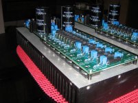
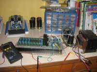
finally 4 channel is alive,
thanks to sir Tony who provided remote assistance from Russia
One thing I've noticed immediately, its a very fine sounding amp - from high, mid to low.
At high volume, I can't hear the amp shouting which you'll normally heard from purchased box
thanks to sir Tony who provided remote assistance from Russia
One thing I've noticed immediately, its a very fine sounding amp - from high, mid to low.
At high volume, I can't hear the amp shouting which you'll normally heard from purchased box
Attachments
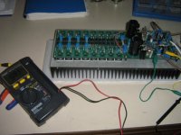
I think the construction manual on Jen's site was not completed. How to calibrate it then? Or did I missed the manual somehow. I am thinking of the same way to do the origianl super leach. Any suggestion?
setting up idle current on the super leach amp should not be any different than that of other ss amps...😀
- Status
- Not open for further replies.
- Home
- Amplifiers
- Solid State
- Leach Super Amp Pcb Re-Design (LSAPRD)