sek has raised an interesting point and one I have overlooked. Would it not have been better to have the transistors mounted outside the perimeter of the board? I can see an advantage of a smaller board and shorter trace lengths as well as lower cost?
Mikett said:Would it not have been better to have the transistors mounted outside the perimeter of the board?
Maybe you should take a look at the size of the traces from and to emitters and collectors of the outputs.
Jens,
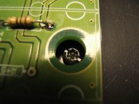
what kind of screws are that, are that washers underneith ?
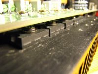
JensRasmussen said:Here is how the transistor is mounted:
Thanks for clarifying, Jens. 🙂
Mikett said:Would it not have been better to have the transistors mounted outside the perimeter of the board? I can see an advantage of a smaller board and shorter trace lengths as well as lower cost?
I don't think so. The trace lengths don't really get shorter (as the distance to "travel" is from the driver stage to the last output transistor, not between the output transistors), but the trace widths would have to be reduced considerably.
I am currently in the process to design a board for a different amplifier, and I found out why it is very difficult to have the output devices on the perimeter of a slim board: How do you route positive and negative supply, power and signal ground, positive and negative base/gate drive, negative feedback and output on a slim strip without letting them interfere with each other? Next to impossible without compromising the amplifier's distortion performance through (too) thin traces and capacitive coupling ...
Just my thoughts,
Sebastian. 🙂
Hi Jens,
I have been wondering what has become of this design. Have you gone any further with it? I have been having nothing but trouble with the amps I tried to make using the foil design off of Dr Leach's wesite. I know others have had success with this but I can't get it to work. I'm sure it is my fault. I did find some mistakes on my part as far wrong values for a few resistors and have fixed those but I stll can't get it to play without distortion. I'm about at wit's end and would like to try your design. I know that you have been spending time on the smaller Leach. Have you given up on the Superamp redesign?
Thanks, Terry
Hi,
I have not stopped working on this yet, but I have been busy on the stardard Leach design.
I'm in the middle of moving at the moment, so PC time is down to a minimum, and I choose to work on the GB for the 6 transistor Leach.
\Jens
I have not stopped working on this yet, but I have been busy on the stardard Leach design.
I'm in the middle of moving at the moment, so PC time is down to a minimum, and I choose to work on the GB for the 6 transistor Leach.
\Jens
Thanks Jens,
I have my name on the list for the 6 transistor boards as well but I want a design that I can use my 90V per rail transformer for. I'll be patient.
Blessings, Terry
I have my name on the list for the 6 transistor boards as well but I want a design that I can use my 90V per rail transformer for. I'll be patient.
Blessings, Terry
jacco vermeulen said:Are we going to tell the Misses, Terry ?
Oh, believe me, she's well aware of the frustration I have been having trying to get these boards working. I think she would welcome some boards that will get this thing up and running. I've had these things spread all over the dining room several times, only to pack it all up again with no solution. I know I've done something wrong, but I just can't find it. The ESP P101 I built sounds lovely. I had hopes this Leach would sound even better. I may never know.
Jen's boards are looking cheaper all the time.
Blessings, Terry
Jens,
Theoretically speaking, how do you plan to see the super leach amp in terms of construction? would you leave the initial and driver stages as the extended leach and just add more power transistors? or do you intend to redesign the whole lot (based of course on the original design)? Obviously since we shall not be using the 15003s there wont be any need to have them in parallel.
I am yet to put together the extended version I got from you but I am sure it will offer superior sound reproduction.
To be honest I have been busy on the leach group buy so I have not had time to do any more work on this project. I have not decided on the final layout of the PCB. I prefer one PCB that has all part on it, while some favor the solution with an input and output board.
During this summer I will be moving (Packing at the moment) so I will have no time for this project until next fall. I will pick up the project then.
\Jens
During this summer I will be moving (Packing at the moment) so I will have no time for this project until next fall. I will pick up the project then.
\Jens
It's an obvious advantage to eliminate wiring => one single pcb is good.
Jens, I have checked the photo of the Leach pcb and unfortunately I must confirm that you have placed the feedback wrong. You sense the voltage at the first transistor pair but the right place is at some point (near the output filter) where you have current from ALL transistors. This will introduce increased distortion but probably not that much. As I promised, I will look over the layout if you want to. More eyes see more.
Jens, I have checked the photo of the Leach pcb and unfortunately I must confirm that you have placed the feedback wrong. You sense the voltage at the first transistor pair but the right place is at some point (near the output filter) where you have current from ALL transistors. This will introduce increased distortion but probably not that much. As I promised, I will look over the layout if you want to. More eyes see more.
No worries Jens. Everyone is expecting you to do something as if you live on diy! what you've done already is commendable anyway.
Per, good idea on the group buy with the parts!
Per, good idea on the group buy with the parts!
Per,
On my extended prototypes I measured the THD to be 0.03% at 0dB (just before clipping) 1kHz into 8 ohm. This is the same FB routing as I have used on the design for the group buy.
\Jens
On my extended prototypes I measured the THD to be 0.03% at 0dB (just before clipping) 1kHz into 8 ohm. This is the same FB routing as I have used on the design for the group buy.
\Jens
That is pretty good but maybe you can trim these values? One way to find out is to measure exactly in the feedback point (where you have no current) rather than at the output.
If it turns out that you will get somewhat better results you can pretty easily patch this on present boards.
If you move the feedback you'll also get a bit lower output impedance.
If it turns out that you will get somewhat better results you can pretty easily patch this on present boards.
If you move the feedback you'll also get a bit lower output impedance.
what about the vas stage?
as far as i can see, another distinction between the leach lo-tim and the leach super amps is the vas stage. it looks like a cascode to me!
what i have read so far are discussions as to why and how to eliminate output transistor stacking.
so to jacko, and djk,
i would like to see some discussions about the vas stage, i suspect this has a lot to do with why i find the leach super amp sound better than the leach lo-tim amp.
Hi Guys,
I wanted to give this thread a boost to remind Jens that a few of us are still interested in this subject. I know Jens is very busy getting his new home in order.
Blessings, Terry
I wanted to give this thread a boost to remind Jens that a few of us are still interested in this subject. I know Jens is very busy getting his new home in order.
Blessings, Terry
- Status
- Not open for further replies.
- Home
- Amplifiers
- Solid State
- Leach Super Amp Pcb Re-Design (LSAPRD)