The 250W-8R amp was all stuff from Self's book and again had options but builders seemed to want to incorporate all of them. There are a few value changes that make the amp very stable and power up okay. An updated fille will be posted soon.
Hi Kevin,
Are you saying you finally built the LTT4 and got it working perfectly with no offset? I have three boards stuffed per your schematic and none of them work. I suppose you got tired of me since you quit answering any of my emails and PMs. I thought it strange that you said above that you don't have any amps that have offset problems when Ranchu and I both tried building this amp and had big offset problems as well as other issues. I'm really interested in seeing your fix for it. They have been sitting on a shelf waiting for a long time now.
Thanks, Terry
OS - can you provide a list of the THD20 figures for your amps? Your site has no data at all.l
The wolverine has a tested 5ppm.
all the others simulate >30ppm.
If you are getting PPB , you must be using ideal current sources and
voltage sources. "Cripple" with true simulated CCS's , Rser=.1 -1 (for
your voltage sources). Add inductances to the rails .... even add
ripple while you simulate performance.
This will reflect real world.
Speaking of the real world - [URL="http://www.chsl.org/soundchart.php"]http://www.chsl.org/soundchart.php[/URL]
Do you run from a vacuum cleaner ? (leave the room -88dba) ?
My speakers are 90+db , as well. But 3 meters away , lower 80's ...
across the room - 70's.
Traffic at my window = 80+ !!
OS
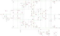
What does R16 do?Hi guys, here is the "supercalifratchilistic" version with the Baxandall super pairs. Its missing a couple of pieces such as the VAS clamps, but I'm interested in your thoughts whether this circuit has any merit over the one at post #1.
2mA through the LTPs (4mA tail current) results in ~1600mV across the VAS degeneration resistors R17 & R18.
That seems very high.
Is there a reason for keeping the collector loads @ 820r?
Last edited:
Came across a Leach amp / JBL circuit inspired using Sziklai pair complementary or ' Compound complementary ' designed amplifer. Rated 350w 4ohms. It was sourced from a local commercial audio component supplier who had standardized his design.
At an initial glance noticed surprisingly low parts count for a discrete Class AB amplifier of this power - with no components underneath the PCB. Tested with 40v-0-40v transformer, 10,000uf x4 capacitor & Peerless 12" 400w subwoofer.
Instead of Toshiba 3x 2SA1943 PNP & 2SC5200 NPN pairs, ON Semiconductor 3x NJW0302G PNP & NJW0281G NPN pairs are used. The driver transistors are 2x A940 & 1x C2073
The heatsink only gets slightly warm on testing. Quite an efficient design. Runs cooler than Darlington complementary design.
An externally hosted image should be here but it was not working when we last tested it.
At an initial glance noticed surprisingly low parts count for a discrete Class AB amplifier of this power - with no components underneath the PCB. Tested with 40v-0-40v transformer, 10,000uf x4 capacitor & Peerless 12" 400w subwoofer.
An externally hosted image should be here but it was not working when we last tested it.
Instead of Toshiba 3x 2SA1943 PNP & 2SC5200 NPN pairs, ON Semiconductor 3x NJW0302G PNP & NJW0281G NPN pairs are used. The driver transistors are 2x A940 & 1x C2073
The heatsink only gets slightly warm on testing. Quite an efficient design. Runs cooler than Darlington complementary design.
Last edited:
This amp better than an ebay Class-D IRS2092 IRFB4227 mosfet amplifier I tested few months back in terms of power output vs. heat dissipation ! I am impressed with this topology.
My experience with a Differential Amplifier http://www.diyaudio.com/forums/soli...ential-input-power-amplifier-ebay-kit-15.html
Darlington complementary vs. Sziklai complementary (Leach amp)
My experience with a Differential Amplifier http://www.diyaudio.com/forums/soli...ential-input-power-amplifier-ebay-kit-15.html
Darlington complementary vs. Sziklai complementary (Leach amp)
Last edited:
What does R16 do?
2mA through the LTPs (4mA tail current) results in ~1600mV across the VAS degeneration resistors R17 & R18.
That seems very high.
Is there a reason for keeping the collector loads @ 820r?
R16 loads the VAS and changes the distortion profile - you can see the effect quite easily in Spice simulation.
I like a VAS Iq >20mA when driving an EF2 so I don't think 1.6V across the 100R degen resistors is excessive. If anything, I would probably like to increase the LTP collector loads to 1k to increase VAS Iq further.
I think it is very good approach. Some say that EF2 sounds the best.
I do not know where exacly is the answer but most important is to build the prototype and listen to it.
I have build several amps with rather lowish THD and they all sound a bit different.
What a disapointment that LTSpice doesn't paly the music too 😀
Came across a Leach amp / JBL circuit inspired using Sziklai pair complementary or ' Compound complementary ' designed amplifer. Rated 350w 4ohms. It was sourced from a local commercial audio component supplier who had standardized his design.
...
At an initial glance noticed surprisingly low parts count for a discrete Class AB amplifier of this power - with no components underneath the PCB. Tested with 40v-0-40v transformer, 10,000uf x4 capacitor & Peerless 12" 400w subwoofer.
...
Instead of Toshiba 3x 2SA1943 PNP & 2SC5200 NPN pairs, ON Semiconductor 3x NJW0302G PNP & NJW0281G NPN pairs are used. The driver transistors are 2x A940 & 1x C2073
...
The heatsink only gets slightly warm on testing. Quite an efficient design. Runs cooler than Darlington complementary design.
Please post the schematic - this is definitely not a Leach amp or derivative, which have far more small-signal components - at least 10 or more small-signal BJTs including symmetric LTP, CCSes, cascodes, etc., per channel.
Secondly, 2 pairs of NJWs will not allow safe operation of a Sziklai OP stage in Class-AB above ~125W. A typical 300W EF2 or EF3 output stage used in a real Leach-type amp requires 4 output pairs. My 350W Leach is designed with *8* output pairs - 4 times more than on this design.
Finally, the efficiency of any Class-AB output stage is capped at about 78% in theory, and is usually below 70% in most practical implementations. There's no way to improve this number, regardless of what is done in the output stage. If it runs cooler than a typical Class-AB, it's probably because it's biased deep in *Class-B*, in which case it will have crunchy cross-over distortion. That's fine for most subwoofer amps, but not for driving speaker loads across the full audible spectrum.
In short, this is probably not a hi-fi amp, but just a modified plate amp or public-address amp which will safely work only up to 125-150W.
Hi Guys
Nothing idealised in my sims or actual circuits, and none of my preferred circuits use active current sources. My goal is always to eradicate distortion, to the point where the AP can't measure it.
That plate amp in post-44 is definitely no leach, and its heat sink is way too small for that kind of dissipation. The 16mm output devices are fine for music with variable level, but most designs for big power use the 20mm packages. Many people think if the amp is fully symmetric that is is a Leach... not quite.
When the load is known, you can do amazing things with very little material.
Have fun
AB class driver stage kits
Hello
greetings many driver stage are kits available on the net tested this
driver stage LABGRUPPEN FP CLONE at 95 volt dc rails +/- peak AC current
40 amps and PEAK ac voltage 45 volts not bad has limiter buit in lcr203
optocoupler
warm regards
Andrew😉
Hello
greetings many driver stage are kits available on the net tested this
driver stage LABGRUPPEN FP CLONE at 95 volt dc rails +/- peak AC current
40 amps and PEAK ac voltage 45 volts not bad has limiter buit in lcr203
optocoupler
warm regards
Andrew😉
Attachments

Yes I checked Leach's designs. The amp I posted is not a Leech design due to the minimalist input stage which consists only of 3x transistors. Just that the output stage is Sziklai complementary inspired by JBL sub amp design. I had a wrong notion Leach made Sziklai pairing in amplifiers famous.
I do not have the schematic with me since I only sourced the board.
I do not have the schematic with me since I only sourced the board.
Last edited:
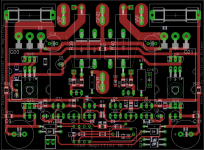
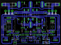
Thanks everyone for your input on this project... I've make a few changes to the original schematic at post #1, including up-rating the catch diodes to MUR460 parts and adding current sharing resistors to the input transistor +IN and -IN connections. The 1N4004 ground lift safety diodes remain, but during construction I'll bypass these with an off-board 35A potted rectifier assembly.
Initial (but incomplete) layout attached. This is a 100x75mm board with output transistors and bias generator sandwiched underneath and a TO-126 spacer on the opposite side. This format has worked very well for me to date and I see no reason to change. PCBs are vertically mounted on the backside of the heatsink and the air gap virtually eliminates any heating effects from the underslung output transistors.
I'll pursue the version with the enhanced VAS as a separate project.
Attachments
I hope you realize your input stage is too fast for the OPS.
Use higher Ft outputs to avoid cross conduction.
Member Vzaichenko fried some 21193/4's in just this manner.
The original leach compensated for low Ft outputs by design ...
yours is more "21'st century".
OS
Use higher Ft outputs to avoid cross conduction.
Member Vzaichenko fried some 21193/4's in just this manner.
The original leach compensated for low Ft outputs by design ...
yours is more "21'st century".
OS
I've been worrying about this and set the ULGF to ~500kHz to try and slow it down for the 4 MHz outputs. Note the 100R LTP degen and 68pF miller caps & also EF2 OPS...
I love the 21193/4 - they are 'tough as old boots' and have a bunch of them lying around. But if you think I'm going to run into dramas I'll use the 30 MHz fT parts...
I love the 21193/4 - they are 'tough as old boots' and have a bunch of them lying around. But if you think I'm going to run into dramas I'll use the 30 MHz fT parts...
Yes, that was exactly the case - fast front-end and 21193/4. Automatic Bode plotter tries to build the phase/frequency response, sweeping up to 1MHz. At around 200-300KHz I had a current shoot-through, killing the output devices... 🙄
Hi Guys
Note the original Leach amp did not have a cascoded front end. He added the cascode so he could increase the rails.
Regarding a fast front-end: it is easy enough to slow down with increased Miller caps. This would not be a problem with the non-cascoded front-end as the MJL2119x has a similar Ft to the original devices Leach used.
Cordell noted that the speed-up cap used in many EF2s/3s can have the opposite effect, which can be the cause of cross-conduction. It is ironic that EF stages were added to most amps in the '70s to speed them up and reduce the likelihood of slew-rate limiting. Here we are seeing a result to the contrary! krglee noted there is plenty of performance available with just an EF2. Bonsai has also tackled the issue by running the VAS at higher currents, just so there is enough drive available. This would seem unnecessary in a push-pull VAS since there is current on demand.
OS - you obviously live in a noisy place. heavy curtains might subdue part of the street noise, but really you should move. You will no doubt suffer from - if not already - the Western 40dB reduced sensitivity in the treble range that is typical for age 65. This is NOT age related, rather almost entirely related to the noise environment.
Esperado mentioned the relativism of his THD results, being useful for comparing his own projects, but not for comparison to others. In a similar vein, the dBA rating system allows wide comparison despite its major flaw of ignoring 3/4 of the noise present. dBC is flat and is what I use when measuring sound fields. C-weighting truly reflects the physiological impact of the noise or music level. Maybe we should start a fund to help OS move to a quieter place?
I don't have to run from my vacuum cleaner as we bought a quiet one. We live in a quiet place after growing up in suburbs. We protect our ears and avoid places that are noisy. We tell those noisy-place operators why we don't go there and suggest how they can tame the noise. I make my amps as noise-free as possible to have all the dynamic range I desire without having to turn it up louder than would be safe.
Have fun
Last edited:
Hi Guys
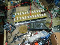
Ranchu32, your board layout is very neat and compact, but I wonder about two details that are in fact related.
The plastic face of the output devices gets hot and is a great place to bolt the thermal tracking element for the bias generator. However, because of how hot this surface can get, it is undesireable to have the device under the board as many do here. Despite the fact some commercial amps are built this way, it is economic but not thermally preferred.
The drivers seem to be bolted to the top of the outputs, so they will be heated beyond their own internal heating value for no real reason. They are being heated and NOT heat sinked. In a small amp like this they don't need a heat sink really, but to be heating them seems ill advised.
The heat from the output stage should be blocked as much as possible from the input stage if one wants DC stability. Even if you choose to run the input devices at high current, they do not have to have high dissipation if you add a cascode. Regardless of cascoding, the input stage diss can be held to more or less its own self-heating temp if it is not being heated by the drivers and outputs. On-board filter caps are often used as a heat shield.
Where tucking the outputs backwards under the input area saves overall space and maybe allows fitment to a smaller heat sink, the output stage heat is now proximal to the input stage, which makes the use of a servo justifiable since it truly becomes a necessary addition.
For many modern layouts using the TO-247, it is necessary to partially cover the package front with the PCB. However, it is mistake to tighten the board down to the transistor face. The leads of the BJT are sturdy and will support the board, especially if there are multiple pairs of outputs. It is easy enough to get everything square and soldered evenly without blocking the cooling paths to the transistor package.
Have fun
Input stage degeneration resistors R6-R9 allow you to measure the current imbalance between Q1&Q2, Q3&Q4. Your DC servo nulls out voltage imbalance but not current imbalance. Fortunately, the emitter resistors in your design make it easy to measure the currents and hence the current imbalance. I suggest you pay extra for 0.1% tolerance resistors in those four positions, and/or hand select them to better than 0.1% with your 4.5 digit ohmmeter. These only cost USD 0.19 in quantity one (link) and they'll give you a way to drastically reduce distortion.
Douglas Self's APAD book discusses the increase in distortion from as little as a 2% imbalance in the current of the input pair. See pp. 130-131 in the 6th Edition and especially Figure 6-6.
Douglas Self's APAD book discusses the increase in distortion from as little as a 2% imbalance in the current of the input pair. See pp. 130-131 in the 6th Edition and especially Figure 6-6.
Input stage degeneration resistors R6-R9 allow you to measure the current imbalance between Q1&Q2, Q3&Q4. Your DC servo nulls out voltage imbalance but not current imbalance. Fortunately, the emitter resistors in your design make it easy to measure the currents and hence the current imbalance. I suggest you pay extra for 0.1% tolerance resistors in those four positions, and/or hand select them to better than 0.1% with your 4.5 digit ohmmeter. These only cost USD 0.19 in quantity one (link) and they'll give you a way to drastically reduce distortion.
Douglas Self's APAD book discusses the increase in distortion from as little as a 2% imbalance in the current of the input pair. See pp. 130-131 in the 6th Edition and especially Figure 6-6.
Hi Mark
I agree with what you say and have already moved to 0.1% resistors in the critical areas around the input filter, feedback network, LTP degen and CM degen. My layouts are predominantly SMT, with a mix of 0805 and 1206 resistors, with TH parts only where the higher Pd is required (such as the feedback resistor).
I'm using the Susumu RG series in the 0.1% 25ppm temp co. range.
http://docs-asia.electrocomponents.com/webdocs/0c1a/0900766b80c1a6c5.pdf
- Status
- Not open for further replies.
- Home
- Amplifiers
- Solid State
- Leach based amplifier design