Hi Guys
With the EF-VAS of the first schematic, the amp is more of a Tigersaurus than a leach. Both are fully symmetric but the Tiger had the EF-VAS in '73. Combined with the EF2 the amp will be fine.
There is no need for the servo if you use high-beta input devices and make the input base-leak resistor the same value as the feedback resistor. DC offset will be sub-milivolt.
Leach did not use current sources or mirrors as he felt they added noise. It can be argued either way if passive current sources (resistors) or active is better: active establishes the final operating currents sooner, which keeps the amp stable as voltages rise and settle; passive allows a thump-free rise/fall but the amp may be unstable during those times - but the rise/fall is short.
Everything does not have to be turned into a cascoded Hawksford Thompson Supercalifratchilistic circuit. Simple circuits have their appeal and their hidden performance attributes. back in the day, builders did not mind putting in some effort and labour to match devices - something that imparts great benefit to performance and eliminates the "need" for many so-called "must-haves" in today's approach.
Have fun
Everything does not have to be turned into a cascoded Hawksford Thompson Supercalifratchilistic circuit.
I think the addition of a few 10c devices is worth the 20 year reliability and
a saved 40$ tweeter here and there.
To be able to grossly overload the input stage for 24 hours and have it
thermally the same as a non-overloaded stage is good.
Funny you mentioned the "tigersaurus" , most of those went up in smoke.
PS - maybe we should all just stick to the "blameless".
OS
why Leach use separate high frequency feedback and low frequency feedback?
"At frequencies above about 150 kHz, C8 and C9 become short circuits. This causes the feedback to be taken from the driver stage instead of from the output. By splitting the feedback into two paths in this way, stability from hgh-frequency oscillations that can be induced by load capacitance is improved."
I contemplated this for the spooky .... but being modular , the OPS would
of needed two FB paths.
Other IPS's might not benefit or be compatible with this scheme .
In regards to using a simple VAS with less degeneration-
1. - By keeping most of the current gain in the input stage and keeping
that gain very constant and linear (CCS's) , THD really stays low ....
even with much less closed loop gain. Amp is "rock solid stable".
2.MUCH less VAS distortion. Doug self -
Distortion in power amplifiers, Part III: the voltage-amplifier stage | EE Times
Shows in Fig. 6 , the cascode at a great magnitude lower THD than "standard".
The 150R on the "spooky" is chosen because of the higher Z cascode.
The speed , elimination of the early effect - Cbc makes the Hawksford
"Supercalifratchilistic circuit" light years ahead of the "standard.
I came to the same conclusions as Cordell and Self - and built it !
OS
Last edited:
No matter the improved load capacitance tolerance from split feedback, you still need an output coil.
How is the Hawksford VAS clipping behavior, my initial simulations show some brutal sticking leading to some nasty spikes.
How is the Hawksford VAS clipping behavior, my initial simulations show some brutal sticking leading to some nasty spikes.
Baxandall super pair
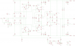
Hi guys, here is the "supercalifratchilistic" version with the Baxandall super pairs. Its missing a couple of pieces such as the VAS clamps, but I'm interested in your thoughts whether this circuit has any merit over the one at post #1.
Hi guys, here is the "supercalifratchilistic" version with the Baxandall super pairs. Its missing a couple of pieces such as the VAS clamps, but I'm interested in your thoughts whether this circuit has any merit over the one at post #1.
Attachments
There's never room to do it right but there's always room to do it over.
Wise words

I'd been wondering about a HEC 'mezzanine' board dropped on top of an existing layout, provided I don't have to chop up the main board to implement the modification.
I started a HEC design last year but set it aside because it quickly become far too complex. I do plan to revisit it in the near future.
Hi Guys
There is no need for the servo if you use high-beta input devices and make the input base-leak resistor the same value as the feedback resistor. DC offset will be sub-milivolt.
Everything does not have to be turned into a cascoded Hawksford Thompson Supercalifratchilistic circuit. Simple circuits have their appeal and their hidden performance attributes. back in the day, builders did not mind putting in some effort and labour to match devices - something that imparts great benefit to performance and eliminates the "need" for many so-called "must-haves" in today's approach.
Hi Struth, good to see you here. I downloaded a copy of your BL20 project from your website when I became interested in the Leach, and nearly had some boards made up, but figured I'd first make a few changes to the basic topology and call it my own.
I'm not obsessed with DC offset precision and I'm quite comfortable with electrolytics in the "signal path". I figured I'd include a servo this time for no other reason than I have never done it before plus I have a bunch of TL072 opamps lying around.
For that matter I'm not particularly obsessed with low THD either, and my favourite amps (TGM8 & simple quasi complimentary designs) probably sound good to me because I like the sound of some harmonic content. I realise this last statement is probably at odds with your view on things, but the reason I'm exploring these more advanced topologies is not because I believe it will lead to a better sounding amplifier, but because it is an interesting intellectual exercise and hobby.
cheers
I very much agree that relatively minimal amplifiers designs such as the Leach have a lot going for them because of their straightforward design. Piling on elaborations have their hazards for limited improvements.
The last SWTPC Tigers were actually pretty decent; I have a pair of Tiger .01s that I acquired for evaluation years ago and use as backup amplifiers. Dan Meyer used a CFP output with a Darlington-like driver on the output transistors. Archived article and schematics here:
.01 | TigersThatRoar
The main power supply capacitors were failing/failed, so I just shotgunned all the electrolytics and most of the carbon film and cheap wirewound resistors with better quality parts. I installed MJ21193/94 output transistors to replace the 70s era devices and observed no problems at all. They could easily drive my 4 ohm Acoustic Research AR-11 speakers.
They sound decent and have been perfectly stable, but the Leach just has more 'air' and perhaps dynamic range, given that the latter has double the output power.
Another reason I like the Leach is that it's got good power supply rejection, given the two stages of RC filtering on the board with zener regulation. I'm now building my amplifiers with star-on-star grounding and .3 ohm resistors in what I call a "weak pi" filter that definitely drops ripple and probably high frequency noise before it gets to the driver board. Never had the nerve or the drive to seriously look at switching supplies when a simple passive supply that's properly grounded and internally isolated works well enough. (Good power supply grounding and layout is an overlooked aspect of amplifier design that's important to get the THD as low as possible.)
Apparently current feedback amplifiers don't have as good a PSSR, so may require a regulated supply for the low power stages, but I've studied only a couple of designs so far.
Way back in the 70s I built a Tigersaurus for a friend, but had only the one unit so I didn't listen to it very much. The end user reported it to be reliable as well as powerful.
The CFP (Sziklai pair - Wikipedia, the free encyclopedia) has a fair reputation, the EF3 is just much more commonly used perhaps because it's easier to implement and may have a higher input impedance. YMMV
--Damon
Hi guys, here is the "supercalifratchilistic" version with the Baxandall super pairs. Its missing a couple of pieces such as the VAS clamps, but I'm interested in your thoughts whether this circuit has any merit over the one at post #1.
Q11/12 can be BCxxx ,as well. You don't need the "clamps" ... it's self-
clamping.
Kypton C and ND as well as Vzaichenko's Valve hybrid use this VAS.
Tested for overload, SQ .... all else.
PS - I'm listening to this circuit now ! "BL20 project" 🙄 - that is the
one that work's with old parts , but oscillates with high Ft ones.
DO NOT build a EF3 this way ... POOF !!
Edit - yer' zeners are backwards , too.
OS
Last edited:
No matter the improved load capacitance tolerance from split feedback, you still need an output coil.
How is the Hawksford VAS clipping behavior, my initial simulations show some brutal sticking leading to some nasty spikes.
Simulations only !!! Actual clipping (on the real amp) shows NOTHING but
very good behavior.
The Baxandall/Hawksford is even better with pico amp Ib and that self
clamp "tube like" clipping.
OS
Another VAS
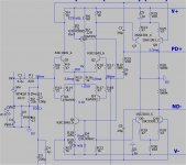
Try this one with the leach.
Self clamping , no saturation .... been
built and tested (but not by me) 😱 .
PS - this one is what I would use with an EF2.
OS
Try this one with the leach.
Self clamping , no saturation .... been
built and tested (but not by me) 😱 .
PS - this one is what I would use with an EF2.
OS
Attachments
Last edited:
Thanks, I see that the clipping is very nice and rounded with the Hawksford VAS, but (in simulation) with very nasty sticking spikes, I am glad to hear that in real life those nasty spikes will likely not happen.
I use the VAS to drive LATfets direcctly, so I need some current in order to drive the COB
haven't seen either them (the sticky spikes) with my mirrored VAS solution. Im pretty much settled on the IPS, but I still have a few options left to try on the VAS part of my circuit. 🙂
I use the VAS to drive LATfets direcctly, so I need some current in order to drive the COB
haven't seen either them (the sticky spikes) with my mirrored VAS solution. Im pretty much settled on the IPS, but I still have a few options left to try on the VAS part of my circuit. 🙂
Last edited:
Tested:
https://anistardi.wordpress.com/2014/12/31/symmetrical-ltp-vas/
Now, I sim high power version with EF3 output and refine it to get better THD and slew rate but still have nice clipping 🙂
https://anistardi.wordpress.com/2014/12/31/symmetrical-ltp-vas/
Now, I sim high power version with EF3 output and refine it to get better THD and slew rate but still have nice clipping 🙂
Thanks OS and bimo. There seems to be almost endless possibilities here!
I wonder if the performance could be improved even more with emitter followers on each of the VAS transistors? Having said that, bimo's simulated 0.006518% THD-20 with the 1381/3503 transistors is not bad at all!
I wonder if the performance could be improved even more with emitter followers on each of the VAS transistors? Having said that, bimo's simulated 0.006518% THD-20 with the 1381/3503 transistors is not bad at all!

Try this one with the leach.
Self clamping , no saturation .... been
built and tested (but not by me) 😱 .
PS - this one is what I would use with an EF2.
OS
Hehe, that was my next layout on the list to try. I thought designed something new... 😀
Hi Guys
OS, your enthusiasm is commendable but you mix issues in a confusing fashion. Are you a lawyer? For example:
"I think the addition of a few 10c devices is worth the 20 year reliability and
a saved 40$ tweeter here and there."
We were talking about the input stage and VAS. The original post mentioned a "modified Leach", and the poster likely never saw a Tigersaurus. Rather, he added the EF to the VAS of a Leach. This has nothing to do with reliability as a plus or minus as reliability of the amp is uneffected by this change. neither is the reliability of a tweeter driven by the amp with these few bits added or nbot.
Protect your tweeters by not clipping the amplifier into it.
"To be able to grossly overload the input stage for 24 hours and have it
thermally the same as a non-overloaded stage is good."
This is something you might do on a test bench but not in real life - unless you have serious mental health issues. Keeping the input stage cool and clear of the heat of the output stage maintains its thermal stability and assures low DC offset drift. No extra circuitry required for this, just proper layout and a good heat sink for the outputs.
For the latter, the use of a tab or L-bracket to mount of output devices to the heatsink while also supporting the PCB is not very good. The edge of the mounting tab gets very hot and heats the components on the PCB quickly. Much better to bolt the devices flat onto the heat sink itself, or onto a flat interface instead of an edged interface.
"Funny you mentioned the "tigersaurus" , most of those went up in smoke."
That happened because of poor heat sinking of the output stage combined with a rather optimistic view of how the amp could be used by both the designer and the users.
My point about the Tigersaurus is simply that it used an EF-VAS and for the day achieved quite good performance. Most hobbyists think Self came up with the EF-VAS but he states that Cambridge Audio was using it as early as 1970.
My point about having to modify every circuit to be the "up to date" version is that there is hidden virtue in many of the simpler designs. Some things don't simulate well but when built properly with carefully selected components provide real-world performance beyond the AP's ability to measure it.
68mV of DC offset? I've never built an amp with offset over 1mV, Leach, Thompson, or other, and no servos or even offset trimpots. Even unselected BJTs in most cases. The amp gain is usually rolled off to unity at DC but the innate DC accuracy is typically very high.
Have fun
Last edited:
Hi Guys
OS, your enthusiasm is commendable but you mix issues in a confusing fashion. Are you a lawyer? For example:
1.-"I think the addition of a few 10c devices is worth the 20 year reliability and
a saved 40$ tweeter here and there."
We were talking about the input stage and VAS. The original post mentioned a "modified Leach", and the poster likely never saw a Tigersaurus. Rather, he added the EF to the VAS of a Leach. This has nothing to do with reliability as a plus or minus as reliability of the amp is uneffected by this change. neither is the reliability of a tweeter driven by the amp with these few bits added or nbot.
Protect your tweeters by not clipping the amplifier into it.
2.-"To be able to grossly overload the input stage for 24 hours and have it
thermally the same as a non-overloaded stage is good."
This is something you might do on a test bench but not in real life - unless you have serious mental health issues. Keeping the input stage cool and clear of the heat of the output stage maintains its thermal stability and assures low DC offset drift. No extra circuitry required for this, just proper layout and a good heat sink for the outputs.
3.-"Funny you mentioned the "tigersaurus" , most of those went up in smoke."
That happened because of poor heat sinking of the output stage combined with a rather optimistic view of how the amp could be used by both the designer and the users.
My point about the Tigersaurus is simply that it used an EF-VAS and for the day achieved quite good performance. Most hobbyists think Self came up with the EF-VAS but he states that Cambridge Audio was using it as early as 1970.
4.-My point about having to modify every circuit to be the "up to date" version is that there is hidden virtue in many of the simpler designs. Some things don't simulate well but when built properly with carefully selected components provide real-world performance beyond the AP's ability to measure it.
68mV of DC offset? I've never built an amp with offset over 1mV, Leach, Thompson, or other, and no servos or even offset trimpots. Even unselected BJTs in most cases. The amp gain is usually rolled off to unity at DC but the innate DC accuracy is typically very high.
"Lawyer" Hmmmm (closing argument) 😀 .
1.- Less Ic does increase reliability. Rounded clipping with 1/10th the H3+
will spare some tweeters.
I have blown some tweeters. Amps that saturate do this real nice.
My two cascoded LED VAS's do NOT , plus the leds optically modulate
to let you see the clipping - neato !
2.- Some do have mental health issues ! Some are poor and use inadequate
PS's and heatsinking. Some play at overload all day in 3rd world ghetto's.
Even here we can design to please.
It seems me and Apex are the only ones who consider this.
3. - http://www.diyaudio.com/forums/solid-state/189970-swtpc-tigersaurus-250w-amp-simulation.html
http://www.swtpc.com/mholley/PopularElectronics/Oct1971/PE_Oct_1971_Pg28.jpg
Besides many a thread on "why did my tiger go up in smoke"? It was the CFP
oscillations that killed them , not just heatsinking.
A lousy design , I am glad my track record is stellar for not having DIY'ers
build fire bombs.
4.- "up to date" ?? HUH ? Many of these designs were made to use
the "devices of the day". Designed to work with JUST those devices , newer
sourcing can oscillate or perform inadequately.
The EF3 is an example of this. Old leach used slow Ft outputs with slow drivers.
Build that today with 10X the Ft - POOF ! (driver decoupling).
Use slow outputs , conversely .... cross conduction.
Offset is usually poor with leach type amps (without matching) , same with
symmetrical CFA designs. P and N are hard to source with consistent beta.
So I add servo's .... devices can also age and change over decades.
We have computers now (simulation) , and can design to even make "sloppy"
sourcing safe with good performance.
All this is done not to be "Fancy" , but to bring a new level of both
resiliency and quality to a "stagnant" hobby filled with "voodoo" like
preconceptions. My record is 100% - NO blown amps to date , full
quick assistance for any "issues" that can arise.
OS
Last edited:
Hi Guys
If you routinely blow tweeters then your system is crying out for biamping.
Or, you are really playing it way too loud and are a deaf lawyer.... must be retired, too, to post so much... a deaf retired lawyer...
Each of our experience is unique to our self.
My experience with DC offset is obviously different than yours, as none of the amps I've built have measurable offset even though they lack DC servos and DC offset adjustments. Maybe angels are supporting the performance despite the corporeal flaws? The amplifier is a servo in its own right, so I don't see the need for adding another one.
The first transistor amp I built blew up but none have since then. You would imply that all those guys who are still using their Leaches, Tigers, Ampzillas, and all the commercial amps from the '70s are living on borrowed time? I think not. If they are not abusing them - as you describe doing with your amps - then the amps will function well for decades.
Besides, with only 1W my speakers are at 90dB - a loudness that is too high to stay in the room. I've measured the power needed in my own system and a 10W amp would be "super" power. To run an amp to clipping means you are deafening yourself and everyone around you. It is foolish in my view to try to reproduce live SPLs at home. You can certainly reproduce the unintelligibility of live sound just by cranking the volume to 10 - pure noise. So, anyone running their amps to clipping really must re-evaluate their system and the purpose of it.
You can advocate adding circuitry to improve performance but in most cases this has no bearing on reliability. Things like emitter degeneration of the input stage are not universally required, despite Self and Bruno suggesting otherwise. Same for base-stops in parallel output stages - not universally required.
Clipping behaviour is certainly something to address but in a correctly configured system no amp will ever clip. Those who argue that clipping is frequent should look at why that it is - most often a poorly chosen system for the room and/or the use of a theatre system for music playback - widely different and a whole other discussion not for here. Some circuits have an inherently soft clipping action with no sticking or oscillation, other circuits need limiting devices or other accesories, none of which is good or bad, just that there are differences.
Simulators are great and I have recently started using LTspice. The circuits I'm working on are all symmetric and have ppb THD20. Nothing fancy but a lot of tweaking of conventional designs. Older designs simulate in the ppm and tens of ppm range. testing into low loads like 1R show higher THD. For a known load, whether low-z or high-z an amp can be designed that is of reasonable size, power, complexity/simplicity, and performance. Schematically it is usually not much different from the high-voltage stuff.
Someone mentioned the BL20. That circuit has flexible compensation - four or five different ways to compensate the amp - and it is not intended that one stuffs all the positions. The zeners are the correct direction.
The 250W-8R amp was all stuff from Self's book and again had options but builders seemed to want to incorporate all of them. There are a few value changes that make the amp very stable and power up okay. An updated fille will be posted soon.
OS - can you provide a list of the THD20 figures for your amps? Your site has no data at all.l
Have fun
- Status
- Not open for further replies.
- Home
- Amplifiers
- Solid State
- Leach based amplifier design