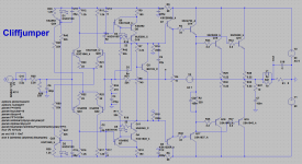
I've been wanting to try a Leach amplifier, and started laying it out in Eagle, originally intending to keep it very close to his original design.
As these things go, I've made quite a number of changes that will probably change the sound profile, but will be an interesting experiment nonetheless.
Hoping that someone here can cast their eye over the schematic and let me know if there's obvious error or omissions that jump out, before I finalise the board design. Similarly, if there is any way to improve performance without adding enormous amounts of complexity I would love to know.
Attachments

Why not layout the PCB to include the option for two pole compensation. Also maybe allow for some lead lag (shunt) compensation on the VAS outputs.
Do the BC560/550s have high enough voltage rating for your design? I see both 25V and 35V rails.
Paul
Do the BC560/550s have high enough voltage rating for your design? I see both 25V and 35V rails.
Paul
mcd99, that's an excellent suggestion to include some options for advanced compensation. I shall do that. What is the consensus on TPC vs. TMC? Are there any 'gotchas' with this topology - almost all the examples I have seen are applied to the standard 'Blameless' topology.
BC5x0 have a 50V breakdown voltage so adequate as input transistors in this design with 35V main rails. The signal transistors subject to full output swing are higher rated 120V KSA992/KSC1845 parts. The 15V subrails are there to power the servo opamp.
BC5x0 have a 50V breakdown voltage so adequate as input transistors in this design with 35V main rails. The signal transistors subject to full output swing are higher rated 120V KSA992/KSC1845 parts. The 15V subrails are there to power the servo opamp.
mcd99, that's an excellent suggestion to include some options for advanced compensation. I shall do that. What is the consensus on TPC vs. TMC? Are there any 'gotchas' with this topology - almost all the examples I have seen are applied to the standard 'Blameless' topology.
I would go for TPC myself. Creates less additional loops (potential problems).
Also, add an option for a cap across R26.
This amp has lots of potential most of which will be unlocked via the compensation.
BC5x0 have a 50V breakdown voltage so adequate as input transistors in this design with 35V main rails. The signal transistors subject to full output swing are higher rated 120V KSA992/KSC1845 parts. The 15V subrails are there to power the servo opamp.
Personally, I like to have my transistors rated for at least twice the supply voltage. Not experienced enough to really comment any further 😉
Paul
I've been wanting to try a Leach amplifier, and started laying it out in Eagle, originally intending to keep it very close to his original design.
As these things go, I've made quite a number of changes that will probably change the sound profile, but will be an interesting experiment nonetheless.
Hoping that someone here can cast their eye over the schematic and let me know if there's obvious error or omissions that jump out, before I finalise the board design. Similarly, if there is any way to improve performance without adding enormous amounts of complexity I would love to know.
You asked , your design won't even sound close to a leach. No EF3 !
Don't let the fear of the triple discourage you (DX) .
OS
mcd99, that's an excellent suggestion to include some options for advanced compensation. I shall do that. What is the consensus on TPC vs. TMC? Are there any 'gotchas' with this topology - almost all the examples I have seen are applied to the standard 'Blameless' topology.
BC5x0 have a 50V breakdown voltage so adequate as input transistors in this design with 35V main rails. The signal transistors subject to full output swing are higher rated 120V KSA992/KSC1845 parts. The 15V subrails are there to power the servo opamp.
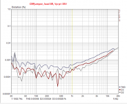
No gotchas ! This topology really does not benefit from advanced compensation.
The slewmaster "spooky amp" is the best with 8ppm THD - just 2 33pf
caps.
A hawksford or other "better" VAS's will benefit this design, but the EF3
is the real SQ ,,as well.
Get a HK990 schematic from electrotanya , it is the most advanced leach
on the planet.
OS
You can try the layout in the link below. The first one points to google drive containing the schematic, BOM and the layout of the PCB. The second link points to the page (in Portuguese) of the author of layout.
https://drive.google.com/folderview?id=0B5nIjMlUyN2nZ0toeTROb0JLUG8&usp=sharing
Nabuco Eletrônica: Leach Amp (Low TIM Amplifier) - Parte 1
https://drive.google.com/folderview?id=0B5nIjMlUyN2nZ0toeTROb0JLUG8&usp=sharing
Nabuco Eletrônica: Leach Amp (Low TIM Amplifier) - Parte 1
Ranchu32
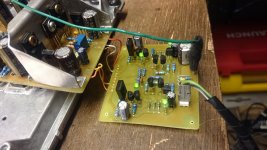
I think OS is right, try the EF3 and some more fancy VAS. I was wondering how does the new VAS from OS and Valery's projects perform and I have made very basic and simple board (just for a fun) and the resaults are stunning.
Or You can try some CFP or yamaha style VAS, only two transistors and nice cliping + very high input impedance (and prapobly ower output impedance so it would be easier to use it with EF2 output stage)
Please take a closer look, You have used 3 transistors per one side of active VAS, 3 transystors can be used in a bit better way.
But I like its simplicy, sipmle can be really beautiful too 😀
Attachments
You asked , your design won't even sound close to a leach. No EF3 !
Don't let the fear of the triple discourage you (DX) .
OS
Definitely don't fear the triple and have built a number of EF3 amps in the past year. The last one had Hexfet outputs, folded drivers and EF predrives and worked nicely. You and Bob Cordell have shown how to stabilise them with base stoppers and judicious rail decoupling.
One of the claimed benefits of a PP VAS is that it is better equipped to drive an output stage, so I figured I would crank up the VAS current a little and put it to the test by loading it with an EF2. But if you think I'm leaving a lot of performance on the table I will definitely reconsider an EF3.
No gotchas ! This topology really does not benefit from advanced compensation.
The slewmaster "spooky amp" is the best with 8ppm THD - just 2 33pf
caps.
A hawksford or other "better" VAS's will benefit this design, but the EF3
is the real SQ ,,as well.
Get a HK990 schematic from electrotanya , it is the most advanced leach
on the planet.
OS
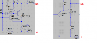
I took a look at your Spooky and the HK990 and one thing that jumped out is that they both use a cascoded VAS instead of the more common (and usually better performing EF VAS) as I have also done here. As I understand it, there is little or no benefit to cascoding a "good" VAS device such as the KSA1381/KSC3503 that already has low Cob and high Early Voltage and can actually make performance worse. You have used the "slow" MJE340/350 in your Spooky and a cascode makes sense there, but in my case with the KSA1381/KSC3503 I'm not convinced that it will improve performance. Or am I missing something here?
Have you tried an EF VAS as shown here?
The other question I have is regarding the VAS Re's. Here I have used 33R (vs. 150R in spooky, Leach, HK990) to help push up the loop gain, but I'm worried that this low value will make the VAS Iq overly sensitive.
Ranchu32
I think OS is right, try the EF3 and some more fancy VAS. I was wondering how does the new VAS from OS and Valery's projects perform and I have made very basic and simple board (just for a fun) and the resaults are stunning.
Or You can try some CFP or yamaha style VAS, only two transistors and nice cliping + very high input impedance (and prapobly ower output impedance so it would be easier to use it with EF2 output stage)
Please take a closer look, You have used 3 transistors per one side of active VAS, 3 transystors can be used in a bit better way.
But I like its simplicy, sipmle can be really beautiful too 😀
Nice schematic and board - WOW a VAS cascoded with a CFP. Is it stable?? 😀
Unfortunately I'm absolutely hopeless in Sim and have no easy way to test my theory that cascoding KSA138/KSC3503 devices brings no real improvement - and may even reduce performance. That's why I went with the EF VAS to try and increase loop gain a little. But I'm nervous, because every Leach style amp I've seen (apart from yours) uses either a simple VAS or cascode!
Thanks borys. The 3rd NPN and PNP in my VAS are current limiting transistors, so they don't do anything in normal operation.
I don't think the 1N4004 is a good choice for D9-12 (in the schematic of post#1). I'd recommend UG4D or MUR460 or 10A05. In my opinion you want 200V or more, 4A or more, 50pF or less.
I substituted ONSemi's Thermal Trak output transistors in one of my Leach amplifier builds with seemingly better audio quality, especially at higher volume where the sound tends to get a little muddy. Used only two TT devices as four was all I had to work with, and two non-TT devices but of the same perforated emitter type and mounted or glued diodes on those, to get the approximate voltages drops needed for thermal bias control. Bias was set with a THD analyzer to minimize crossover distortion, but no more than that to also minimize heat dissipation--the amplifier runs only slightly warm. I could drop the distortion down to my analyzer's residuals of about .002% over the middle of the audio range; above 5 kHz distortion rises in the typical Lin topology manner to around .1%. No other changes were made to the circuit.
I can't account for the subjective improvement in the sound except that the output transistors are faster and more linear under load, which is always a weak area in bipolar transistors--gain drops off with more/faster current.
Leach implemented cascoded VAS in his high power amplifier, but I'm reading through Cordell's book that the measured reduction in distortion is slight. The limitation of the Lin topology is that feedback has to drastically drop at higher frequencies for stability, and so the Class B crossover distortion can't be fully eliminated, especially at high frequencies.
Getting around that fundamental limitation would mean a major change in basic topology, and Leach's design pretty much does all that can be done everywhere else. Despite the claims of some, I feel like the EF3 output stage is very stable and is an excellent compromise to minimize loading the sensitive VAS stage. A cascoded VAS and a CFP output sounds rather sporty, might be worth the experiment.
Hawksford error correction looks like a good step forward for cleaning up the Class B crossover distortion and high frequency distortion. I've also got a friend's driver boards for a current feedback amplifier design, to wire up and see how it works.
--Damon
Thanks Damon, you have made some interesting points here, plus another vote for EF3.
Advanced compensation schemes should improve loop gain at higher frequencies, but OStripper has stated that this topology doesn't really benefit. 8ppm THD is pretty impressive anyway...
Advanced compensation schemes should improve loop gain at higher frequencies, but OStripper has stated that this topology doesn't really benefit. 8ppm THD is pretty impressive anyway...
There's never room to do it right but there's always room to do it over.... assuming I have the board space (it is very tight) I will make the switch.
Also ask yourself whether ground fault protection diodes D1 and D2 really ought to be 35 ampere devices (part of a GBPC3510 bridge rectifier assembly).
I'd been wondering about a HEC 'mezzanine' board dropped on top of an existing layout, provided I don't have to chop up the main board to implement the modification. I haven't been able to give it much thought; I really need to learn how to use a good SPICE simulator...
At any rate, the Thermal Trak transistors seemed like a very effective upgrade and didn't appear to introduce any instability despite the devices' much higher Ft.
Anyone have recommendations for potentially better driver transistors for the Leach amplifier?
I've also tried a speedup capacitor across the driver emitters, but there was little change in distortion readings, even looking at the residuals on an oscilloscope.
Anyone look at Benchmark's new amplifier? It has ridiculously low distortion readings even at 20 kHz and using a Class H output stage--it uses an error correction circuit a la' Hawksford. Also has a switching power supply and is remarkably compact and lightweight. I've wondering for a couple of decades about my next amplifier project, but Leach's design has always worked so well for me that I've had a hard time identifying a good amplifier design to move onto that gets around the limitations of the Lin topology and a practical Class B output stage. HEC and current feedback amplifier design are what I'm studying now; someone needs to kick me in the caboose to wire up that CFA board and see if my friend's design is viable. It ought to be really fast, if nothing else.
Definitely don't fear the triple and have built a number of EF3 amps in the past year. The last one had Hexfet outputs, folded drivers and EF predrives and worked nicely. You and Bob Cordell have shown how to stabilise them with base stoppers and judicious rail decoupling.
One of the claimed benefits of a PP VAS is that it is better equipped to drive an output stage, so I figured I would crank up the VAS current a little and put it to the test by loading it with an EF2. But if you think I'm leaving a lot of performance on the table I will definitely reconsider an EF3.
I took a look at your Spooky and the HK990 and one thing that jumped out is that they both use a cascoded VAS instead of the more common (and usually better performing EF VAS) as I have also done here. As I understand it, there is little or no benefit to cascoding a "good" VAS device such as the KSA1381/KSC3503 that already has low Cob and high Early Voltage and can actually make performance worse. You have used the "slow" MJE340/350 in your Spooky and a cascode makes sense there, but in my case with the KSA1381/KSC3503 I'm not convinced that it will improve performance. Or am I missing something here?
Have you tried an EF VAS as shown here?
The other question I have is regarding the VAS Re's. Here I have used 33R (vs. 150R in spooky, Leach, HK990) to help push up the loop gain, but I'm worried that this low value will make the VAS Iq overly sensitive.
I'm running the 3503/1381's.
You never simulated a "plain" VAS versus the cascoded one ?
(340/350 or 3503/1381)
THD drops by almost a factor of ten.
The cascoded VAS also has a tame saturation (clips nicer).
Never tried the super pair /cascode combo on the leach , it self clamps
with NO saturation.
OS
The cascode has an inherent, high output impedance.I took a look at your Spooky and the HK990 and one thing that jumped out is that they both use a cascoded VAS instead of the more common (and usually better performing EF VAS) as I have also done here. As I understand it, there is little or no benefit to cascoding a "good" VAS device such as the KSA1381/KSC3503 that already has low Cob and high Early Voltage and can actually make performance worse. ..............
The cascode must be loaded in such a way that the high output impedance does not deteriorate the performance. That usually requires a very high receiver impedance.
A normal VAS has a much lower output impedance and the circuit loading that happens to suit this plain VAS (or EF+VAS) does not necessarily suit throwing in a cascode.
ostripper said:You never simulated a "plain" VAS versus the cascoded one ?
(340/350 or 3503/1381)
THD drops by almost a factor of ten.
I'm absolutely hopeless when it comes to using simulators, so I try to understand the theory and then make manual calculations or in an Excel spreadsheet.
I'm making a version with Baxandall super pairs and will post it up later today.
AndrewT said:The cascode has an inherent, high output impedance.
The cascode must be loaded in such a way that the high output impedance does not deteriorate the performance. That usually requires a very high receiver impedance.
A normal VAS has a much lower output impedance and the circuit loading that happens to suit this plain VAS (or EF+VAS) does not necessarily suit throwing in a cascode.
I suspect that you are correct Andrew; I believe Bob Cordell is his book commented that a VAS cascode did not make much sense unless it was loaded with a very high impedance output stage (bipolar EF3 in his example).
- Status
- Not open for further replies.
- Home
- Amplifiers
- Solid State
- Leach based amplifier design