Hello.
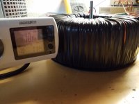
I'm firing up this leach super amp slowly, and adjust bias, right now it's on a vario only +/÷ 60volt, I measure bias on four 1 ohm resistors between supply cap and driver board, its steadily ideling, but my concern is the power draw from mains,
Its using 70 watts already, and that number will go past 100 watts when raising rails, to their normal which is +/÷ 70 volts, I use lever voltage transformer than specified by the doctor, but still I am concerned about this current draw.
Inputs are shorted output have 6.8 ohm resistors across.
Am I to worry, ?
Scoped it last week single channel on bench supplies, traces looked clean.
Perhaps it's just my ptsd kicking in I'm not happy about high voltages, transformer is buzzing, it was originally giving 75 volt ac, took some wiring of and brought it down, so probably loose, it's a 2kw core
Attachments

Last edited:
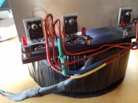
Voltages look equal after rectifier, but the large toroidal transformer is heating up, it has 4 independent secondarys, its wired as dual mono.
It's now on full 230v on primary side, I have adjusted ideling up to 50ma per 1 ohm resistor, amplifier is using 75 watts in total.
It's now on full 230v on primary side, I have adjusted ideling up to 50ma per 1 ohm resistor, amplifier is using 75 watts in total.
Super Leach has some sneak currents in there - biasing up that mid-point voltage for the output/driver stage. Therefore it’s idle current will be on the high side, even if youre not measuring squat across the emitter resistor.
If your trafo is heating up (but the amp behaving normally) I’d be looking into the power supply by itself first. Sounds to me like you’re hitting the primary too hard if it’s ”buzzing”. In order to get toroids to buzz due to the load current (which they will do) the load has to be substantial. The amp would be getting HOT (hotter than the blazes of hell and damnation hot) and your ears would be ringing from the loud music.
If your trafo is heating up (but the amp behaving normally) I’d be looking into the power supply by itself first. Sounds to me like you’re hitting the primary too hard if it’s ”buzzing”. In order to get toroids to buzz due to the load current (which they will do) the load has to be substantial. The amp would be getting HOT (hotter than the blazes of hell and damnation hot) and your ears would be ringing from the loud music.
Is your transformer truly specified for 230V? Some older ones have a 220V primary and can give problems with the mains voltage topping out at 240-250V these days. The core saturates resulting in high idle current draw, heating up and sometimes mechanical hum. Most older 220V ILP and Amplimo handle this badly. Solution is to add a few primary turns.
The transformer is a 220 v ac model, but with the vario on 220v it's almost as loud.
I have installed some bleeder resistors but they shouldn't matter ,6k8, some 12 ma.
I think I will disconnect it from load, and see how much its pulling, capacitors are not brand new they also have some leakage, but can't be much.
Maudio.. add primary turns?, primarys are the inner windings , would be a challenging job, as said still buzzing and 10-15 degrees over ambient temp, its weight is 14 kilos.

Start by putting 10 or so windings on the core and measure the AC voltage that this produces. That will give you a good estimate of the V/turn ratio so you can calculate the required number of turns to add to the primary.
Sounds like a plan, I believe I have some heavy enameled copper somewhere.
One more thing, the cause of this core saturation, is that because I removed some secondary winding?
Also is there a method to check? Other than the humming and heat.
One more thing, the cause of this core saturation, is that because I removed some secondary winding?
Also is there a method to check? Other than the humming and heat.
Better use plain pvc insulated wire, it's safer in this application. And easier.
The cause of core saturation has nothing to do with the number of secundaries. It's basic physics. Depending on the core material there is a max flux density the core can handle before saturation. A mains transformer is usually designed to operate close to saturation point, to minimize required core size. So it will quickly saturate above the rated input voltage.
When you draw a graph of input current vs input voltage for an unloaded transformer, you will see the current steeply rise from a certain point onwards. That's where saturation sets in.
If you put the unloaded transformer on a dim bulb and it DOESNT go completely out then the magnetization current is likely too high (saturation) and it will hum and get hot. Add (enough) turns, problem goes away.
For me (where 60 Hz rules) even the 1500 VA Anteks are silent, and don’t draw enough to see a glow at all on a 100W dim bulb.
For me (where 60 Hz rules) even the 1500 VA Anteks are silent, and don’t draw enough to see a glow at all on a 100W dim bulb.
Great tip wg. I have planned to disconnect it from capacitor banks and see its actual current draw.
I hope that it still is good inside, no crisp windings, this really sets my project back, all wiring is done, all holes drilled.
Wish I had a insulation tester.
I hope that it still is good inside, no crisp windings, this really sets my project back, all wiring is done, all holes drilled.
Wish I had a insulation tester.
Okay, it seems to be working fine, it uses 10 watt alone, so it seems to be an error I made with its connection to rectifiers.
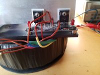
It has four independent 56 volt taps, they way I did it is with two full bridge rectifiers made up from mur3020, two taps went together and formed ground, is it a phase or two I got backwards? If yes do I just try out another combination ? Or is there a trick?.
4 individual bridge rectifiers perhaps,? No currents mismatch.
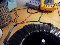
Last photo are the 4 secondary pairs, 0.2 ohm between them
It has four independent 56 volt taps, they way I did it is with two full bridge rectifiers made up from mur3020, two taps went together and formed ground, is it a phase or two I got backwards? If yes do I just try out another combination ? Or is there a trick?.
4 individual bridge rectifiers perhaps,? No currents mismatch.
Last photo are the 4 secondary pairs, 0.2 ohm between them
Attachments
Last edited:
A phase or two backwards if you paralleled them wouldn’t draw a little extra current. It would draw A LOT extra current and trip the breaker in the panel. What you may have is a mismstch in the number of turns, resulting in a circulating current. Correct this if you are paralleling any windings. Or use 4 independent bridge rectifiers, and use that to create two separate +/- power supplies, powering the channels independently. A volt or two mismatch won’t even be noticed on +/-80V supplies.
I would not use epitaxial rectifiers for a 60 Hz power supply this large. The surge currents from charging 20,000 uF capacitors every time you turn it on is not good for them and will run it over their at most 300 A single-cycle current rating. Eventually they die. The higher FREQUENCY in proper switch mode power supplies results in shorter charging pulses which high speed rectifiers can handle. For this application, switch to regular metal cased standard recovery block rectifiers. That’s what’s made for this. Put a .1 uF 1000 volt ceramic cap (or X-rated 630V MYLAR not polypropylene film cap) in parallel with the secondary, attached directly to the two ~ terminals on the bridge instead. That will prevent transformer ringing with a very large toroid of this type. Don’t go putting in audiophile caps here! Class 2 ceramics or regular Mylar have just the right amount of ESR to make a built in snubber resistor so you don’t need to add it. Put in “ideal” caps and it’s worse than without it, unless you add 5 or 10 ohms.
I would not use epitaxial rectifiers for a 60 Hz power supply this large. The surge currents from charging 20,000 uF capacitors every time you turn it on is not good for them and will run it over their at most 300 A single-cycle current rating. Eventually they die. The higher FREQUENCY in proper switch mode power supplies results in shorter charging pulses which high speed rectifiers can handle. For this application, switch to regular metal cased standard recovery block rectifiers. That’s what’s made for this. Put a .1 uF 1000 volt ceramic cap (or X-rated 630V MYLAR not polypropylene film cap) in parallel with the secondary, attached directly to the two ~ terminals on the bridge instead. That will prevent transformer ringing with a very large toroid of this type. Don’t go putting in audiophile caps here! Class 2 ceramics or regular Mylar have just the right amount of ESR to make a built in snubber resistor so you don’t need to add it. Put in “ideal” caps and it’s worse than without it, unless you add 5 or 10 ohms.
In a few words, it is a poorly executed power supply, I see that now, I have ordered 4 KBPC5006 bridges, and will put those mur3020 to use elsewhere.
Thanks for taking your time, I was getting pretty tired of this amp project, now I'm more confident, since I know that the leach modules perform flawlessly.
Thanks for taking your time, I was getting pretty tired of this amp project, now I'm more confident, since I know that the leach modules perform flawlessly.
I built my original Low TIM in 1977 using permanent markers for etching my own boards. 4 years later fully regulated those with Boak Sulzer in a monoblock arrangements using Radio Shack transformers as boosters for the transofrmers to the the prereg voltage up. Next was a Double Barrel Amp using 4 500VA Toroids because those were all I could get. Fully rectified I was getting 100V rails regulated down to 85V rails. That was 1984-85. Was completed when I returned to post grad Bschool. After I took over a project that was incomplete from a friend who was building the Low TIM III, traded some skis for his project. I fully regulated those. The Double Barrel is in the corner stored. Using the Low TIMIIIs as subwoofer amp for the RSS390HF sealed with a miniDSP.It seems the leach amp still means a lot to a lot of people 🙂
Next I am thinking of using the Double Barrel for the Subs. The Low TIM IIIs for 50-300Hz, AHB2s for the 300-3000Hz, Mod 86 for the BE tweeters and up. All in nested array. Can't decide on Textreme or BE, and Textreme or Ceramic for mids. Driven by Flex 8.
Yeah those Leaches mean a lot to me.
amplidude - I can't see the transformer mounting in your first photo. Make sure that the metal bolt passing through the center does not form a shorted turn.
Mikett - We all need to thank Leach that we are not listening to crossover distortion "fixed" by negative feedback.
Ed
Mikett - We all need to thank Leach that we are not listening to crossover distortion "fixed" by negative feedback.
Ed
- Home
- Amplifiers
- Solid State
- Leach amp with 2SA1386A and 2SC3519A