Scl and sda are pulled to vcc with 2k2 resistors so they should be around 5v. Make sure you modified oled without any errors. It seems that scl and sda are messing with i2c bus preventing arduino from booting.
That what I was thinking. The modifications of the old OLED seem ok so I'm just going to wait for the new oled. Until then I'm going to wine country.
That what I was thinking. The modifications of the old OLED seem ok so I'm just going to wait for the new oled. Until then I'm going to wine country.
You can try putting a cap of around 1000uF on D+ line, in case you have garbage injected from OLED.
Another display that works with this project, requires no additional components to be soldered and cheapest I could find:
White 2.42" 2.42 inch LCD Screen 12864 OLED Display Module IIC I2C SPI Serial for C51 STM32 SSD1309-in Integrated Circuits from Electronic Components & Supplies on Aliexpress.com | Alibaba Group
White 2.42" 2.42 inch LCD Screen 12864 OLED Display Module IIC I2C SPI Serial for C51 STM32 SSD1309-in Integrated Circuits from Electronic Components & Supplies on Aliexpress.com | Alibaba Group
Sorry folks, there has been an error in how to do a hardware mod on your displays. You MUST NOT pull DC to VCC, otherwise you will set I2C address to 0x3D, and firmware looks for 0x3C. So the correct instructions are below:
R4 - remove
R3, R5, R7 - 0R (short with blob of solder)
RES - connect to VCC with 10K resistor (pullup)
RES - connect to GND with 10uF cap (keeps RES low during display power up)
R4 - remove
R3, R5, R7 - 0R (short with blob of solder)
RES - connect to VCC with 10K resistor (pullup)
RES - connect to GND with 10uF cap (keeps RES low during display power up)
Sorry folks, there has been an error in how to do a hardware mod on your displays. You MUST NOT pull DC to VCC, otherwise you will set I2C address to 0x3D, and firmware looks for 0x3C. So the correct instructions are below:
R4 - remove
R3, R5, R7 - 0R (short with blob of solder)
RES - connect to VCC with 10K resistor (pullup)
RES - connect to GND with 10uF cap (keeps RES low during display power up)
Thank You for the update !!!!!!!!
Powered up and calibrated but im going to get some clips for the ldrs I just could not get a proper hold of them.
Paul
Thank You for the update !!!!!!!!
Powered up and calibrated but im going to get some clips for the ldrs I just could not get a proper hold of them.
Paul
There are big holes next to each ldr used to stick your probes for measurements
There are big holes next to each ldr used to stick your probes for measurements
Awesome!!!! thanks again
Do The parameters need to be changed ? They are all set to min of 40 or do I need to set their actual measured values are lowest of 40.5 and highest 52 my D+ is 5.06
Yes, you need to set min values. You can measure them while in set menu and put values directly in.
So after 2 days of testing ( and working great) I woke up this morning and I noticed the unit was frozen up so I rebooted now the screen sometimes lights up with garbage or with one or two lines showing and no ir response. I have my new oled coming maybe thats the issue Im not sure.
So after a little bench testing I swear its the oled, if i turn on the unit (hold down play button)with garbage on screen the relays chatter (sometimes)if i remove the oled I can hear the unit turn on and i can cycle through inputs ( relays switching tested with DMM) without any issues. Voltages seem fine 5vdc across all inputs and it works (its actually usable) except for oled not coming on.Tried a capacitor across D, nothing. Oh well I guess its just a waiting game for now.
Hi Zdr
I have been using my ldr mk2 for the past 2 months now and it is going well but. When I compare to my previous ldr, this one has a higher noise floor. Are there any modifications I can do to try and lower the noise floor? I am guessing it may be dac/arduino noise coming through the system. I just tried moving the power supply away from the main board but that made no difference. I did also add 1000uf capacitors to each of the 3 5v power supply output terminals but that didn't do much either.
I have been using my ldr mk2 for the past 2 months now and it is going well but. When I compare to my previous ldr, this one has a higher noise floor. Are there any modifications I can do to try and lower the noise floor? I am guessing it may be dac/arduino noise coming through the system. I just tried moving the power supply away from the main board but that made no difference. I did also add 1000uf capacitors to each of the 3 5v power supply output terminals but that didn't do much either.
@zdr.
Can a 50Hz mains filter be put into the software code to help lower the idle noise of the LDR passive pre?
Can a 50Hz mains filter be put into the software code to help lower the idle noise of the LDR passive pre?
@zdr.
Can a 50Hz mains filter be put into the software code to help lower the idle noise of the LDR passive pre?
I’m not sure what you mean. I don’t hear any noise in my setup.
Hi Zdr
When I havent got any music and turn the volume up on the LDR then the noise floor increases. I have made this a little bit better by connecting my metal chassis to the 0v dc point at the power supply board. It is worst between 25-49 level of volume but when it reaches 50, the noise disappears. My mains supply is 50Hz so I was thinking maybe the arduino can be programmed to reject this 50Hz noise somehow?
When I havent got any music and turn the volume up on the LDR then the noise floor increases. I have made this a little bit better by connecting my metal chassis to the 0v dc point at the power supply board. It is worst between 25-49 level of volume but when it reaches 50, the noise disappears. My mains supply is 50Hz so I was thinking maybe the arduino can be programmed to reject this 50Hz noise somehow?
I don’t see how could 50Hz noise possibly get into audio signal, since audio ground and digital ground are not connected. There is also no connection between any of the supply lines and audio signal. It could be entering audio path through other parts of the system though.
In the original thread forum member "nikosokey" had same problems as I have. That is he was getting noise. This is seen here
https://www.diyaudio.com/forums/ana...urce-selection-controller-50.html#post4849058
You did actuaally reply to him zdr.
Nikosokey says he did fix his noise problem by connecting chassis gnd(earth) to 0v power supply gnd. Which is what I have done as well.
Mains frequency hum will almost certainly be there on most amplifiers and preamplifiers in varying amount depending on the quality of the power supply/filters/circuit etc.
I ask you to do this. turn your amplifier and ldr on then with your ear to your speaker start to turn the volume on the ldr passive pre up. You will hear the noise floor through your speakers when it is turned up right. This is the noise I am talking about. I find it is loudest between ldr volume levels 25-48 (gradually increasing) then when it reaches 50(max) the noise floor I did hear suddenly "dissapears". Can someone explain why this happens?
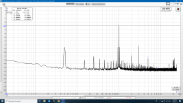
Now lets show some FFT plots I have done.
This is without the chassis to ov/gnd connected. We can easily see a high 50Hz Harmonic as well as a fairly high 3rd harmonic as well. Not to mention all the other harmonics in there.
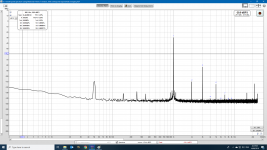
So now the chassis to ov is connected and it is looking much better. The 50Hz has dropped and alot of other noise is also decreased. 3Khz (3rd) harmonic is still higher than 2nd harmonic 2KHz.
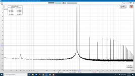
Here is my signal generator only. 3rd order harmonics are lower than the 2nd order here.
https://www.diyaudio.com/forums/ana...urce-selection-controller-50.html#post4849058
You did actuaally reply to him zdr.
Nikosokey says he did fix his noise problem by connecting chassis gnd(earth) to 0v power supply gnd. Which is what I have done as well.
Mains frequency hum will almost certainly be there on most amplifiers and preamplifiers in varying amount depending on the quality of the power supply/filters/circuit etc.
I ask you to do this. turn your amplifier and ldr on then with your ear to your speaker start to turn the volume on the ldr passive pre up. You will hear the noise floor through your speakers when it is turned up right. This is the noise I am talking about. I find it is loudest between ldr volume levels 25-48 (gradually increasing) then when it reaches 50(max) the noise floor I did hear suddenly "dissapears". Can someone explain why this happens?
Now lets show some FFT plots I have done.
This is without the chassis to ov/gnd connected. We can easily see a high 50Hz Harmonic as well as a fairly high 3rd harmonic as well. Not to mention all the other harmonics in there.

So now the chassis to ov is connected and it is looking much better. The 50Hz has dropped and alot of other noise is also decreased. 3Khz (3rd) harmonic is still higher than 2nd harmonic 2KHz.

Here is my signal generator only. 3rd order harmonics are lower than the 2nd order here.

Some more distortion graphs.
This 1st pic is using my 1st ldr passive pre by "Rudi" as shown in this thread
Versatile and comfortable passive pre-amp
THD - 0.073% This volume level is equivalent to around around 44 on the new ldr attenuator(zdr type).
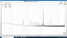
Now the next few pics are with the second smarter ldr as shown in this current thread.
Volume level 9. THD-0.29% although it is not really heard at this low volume.
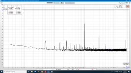
Volume level=35 This is loud and about the level I play my music at

Volume = 44. This is the level I was testing when you can see the 1KHz harmonic at -30db
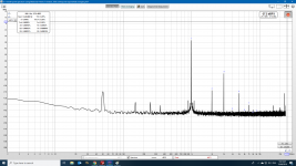
Vol=48 We can see THD dropping as we near the maximum volume.
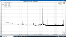
Vol=49 Distortion lowering more.

Vol=50 Maximum volume. Now is when I hear no noise on my speakers. Also distortion is only THD- 0.011% and also now 3rd harmonic is lower than the 2nd harmonic.
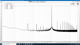
A thing to note before people ask. These measurement were done with only my signal generator connected to a ldr passive pre (old or new type) and then to my behringer mic mixer/sound card as shown on this thread by xrk971.
Howto - Distortion Measurements with REW
This 1st pic is using my 1st ldr passive pre by "Rudi" as shown in this thread
Versatile and comfortable passive pre-amp
THD - 0.073% This volume level is equivalent to around around 44 on the new ldr attenuator(zdr type).

Now the next few pics are with the second smarter ldr as shown in this current thread.
Volume level 9. THD-0.29% although it is not really heard at this low volume.

Volume level=35 This is loud and about the level I play my music at

Volume = 44. This is the level I was testing when you can see the 1KHz harmonic at -30db

Vol=48 We can see THD dropping as we near the maximum volume.

Vol=49 Distortion lowering more.

Vol=50 Maximum volume. Now is when I hear no noise on my speakers. Also distortion is only THD- 0.011% and also now 3rd harmonic is lower than the 2nd harmonic.

A thing to note before people ask. These measurement were done with only my signal generator connected to a ldr passive pre (old or new type) and then to my behringer mic mixer/sound card as shown on this thread by xrk971.
Howto - Distortion Measurements with REW
My reply was about the “volume bump” which was present in original design. I will check the buzzing noise when I get back from vacation on 23rd. In theory, I really don’t see how can any signal pass over to audio part, as it’s galvanically isolated. Only during calibration the two grounds are connected with the relay.
- Home
- Source & Line
- Analog Line Level
- LDR Pre MkII - LDR volume control and I/O switching