That’s a relay bypass I guess. You will either have a relay or a ldr in signal path. Some prefer one to the other.
Last edited:
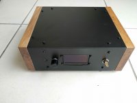
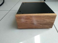
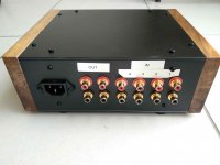
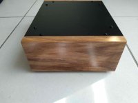
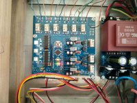
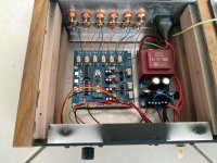
Here are some pics of the finished product. I have found that on previous LDR attenuators I have built that the centre balance can move over time. Since this has calibration smarts, it will be able to be recalibrated if needed again at a later stage. Thanks for providing this project ZDR.
Attachments
-
 IMG_20190702_084851.jpg445.9 KB · Views: 510
 -
 IMG_20190702_084914.jpg649.6 KB · Views: 486
 -
 IMG_20190702_084936.jpg500.2 KB · Views: 471
 -
 IMG_20190702_085001.jpg607.6 KB · Views: 487
 -
 IMG_20190702_085102.jpg460.5 KB · Views: 479
 -
 IMG_20190702_085416.jpg934.9 KB · Views: 353
 -
 IMG_20190702_085433.jpg944.9 KB · Views: 365
Just getting ready to put mine together a couple of questions though
1. can the 2 resistors under the arduino be soldered on the backside of the pcb ?
2. is there a way to set this up through a pc since my OLED will not be here for a while?
Thank You
1. can the 2 resistors under the arduino be soldered on the backside of the pcb ?
2. is there a way to set this up through a pc since my OLED will not be here for a while?
Thank You
Just getting ready to put mine together a couple of questions though
1. can the 2 resistors under the arduino be soldered on the backside of the pcb ?
2. is there a way to set this up through a pc since my OLED will not be here for a while?
Thank You
1. yes
2. no
Could someone post a picture of the ps board from the rectifier side preferably one for 110VAC. I am not getting any voltage to my rectifiers but I've got voltage on my secondaries. I see other jumpers but cannot find any information on them.
On the PSU PCB, the 2 resistors are labeled 20k, yet the PS BOM calls out 10k. What is the correct value that should be used? Also, do the 7805s require heatsinks? Seems the silkscreen indicates those u-shaped HS are indicated.
Ok
I got my lcd 1309 version did the modifications to it, but on power up it does not light up. I've got 5.0 vdc at VCC and GND now where can the fault be? Where should I start looking?
I got my lcd 1309 version did the modifications to it, but on power up it does not light up. I've got 5.0 vdc at VCC and GND now where can the fault be? Where should I start looking?
I have continuity between sda and sdl from the arduino and the header. I tried to put 5vdc to red and black and still nothing. Should the BKL wire be hooked up somewhere?
Honestly I think the LCD is faulty I fully expect something to happen on the screen whether good or bad. I think I may just order the wide.hk one.
Also I notice if I power up the unit without the screen attached the lights on the arduino all light up for a few seconds then only the green stays on. With the screen attached only the green comes on.
Bkl shouldn’t be wired anywhere. Display will remain black if there are errors anywhere. You should check all three power lines.
Ok a little troubleshooting on the oled
vcc to gnd 5.02 vdc
SDA to gnd 5.02 vdc -------sda pin to pin out 2.2k
SCL to gnd 5.02 vdc -------scl pin to pin out 2.2k
shouldn't the scl and sda be around 3.3 vdc?
I do notice that if the yellow and orange are hooked up to the oled no relays click and only the green light come on the arduino
without yellow and green TX and RX come on for a few seconds then go to green only and i hear a relay(s) click
Shorting the yellow and orange also produces a green arduino light only(no oled hooked up) hence my assumption that the oled is faulty.
I have taken the arduino reflashed and resoldered it back in and have also reflowed all other connections, still no good results.
I have ordered the wide.hk oleds with hopes that it is the OLED.
Last edited:
Scl and sda are pulled to vcc with 2k2 resistors so they should be around 5v. Make sure you modified oled without any errors. It seems that scl and sda are messing with i2c bus preventing arduino from booting.
- Home
- Source & Line
- Analog Line Level
- LDR Pre MkII - LDR volume control and I/O switching