I spent a very good sum of money getting this preamp repaired from a tech, which he did, but it still hums and it's way too loud for me to live with. It hums with volume all the way down, on any source, and without any components connected besides an amp. There is no ground prong on the power cord of the pre or the power amp.
You guys have any thoughts? It looks like he replaced some diodes in the main power supply of this thing and he twisted 3 small ones together in parallel to apparently match the required rating of the original single diode.
I do have a scope, which I don't really know how to use.
I could take it back to him again, but he had the preamp for a LONG time (just over a year) and there is no way I am dealing with him again. Are there any obvious sources to check for hum? This uses an outboard PSU and it's well laid out and easy to get to the components.
I would like to rule out anything easy or obvious (such as diodes). It seems to be 60hz hum and it does it even if I swap tubes.
Thanks guys.
Is any of your two prong devices non-polarized? if so, may I suggest to you to turn around the plug.
on tube gear, I try and encourage to use non-polarized plugs. The reasons behind this is: when I get a hum on something that did not do it on my isolation transformer/variac about 60% of the time the 3rd prong was the culprit. Sometimes, I'll incorporate a ground lift switch on the 3rd prong. 40% of those instances is power leakage from the transformer on the ground causing the hum. Turning around the plug fixes these.
Can you post some pics of the componate side of the power supply chassis and pre amp chassis?
1 paralleling diodes is BAADDDD. They are not resistors and do not auto load balance.
2. for the hum, the easiest thing is to lift the heater voltage above ground. The cap is optional but recommended, or use 2 small mkv caps on both sides of the heater as steve does it.
http://i573.photobucket.com/albums/ss171/jonnyeye/filrefvoltage.gif
DCPP Amp
2. for the hum, the easiest thing is to lift the heater voltage above ground. The cap is optional but recommended, or use 2 small mkv caps on both sides of the heater as steve does it.
http://i573.photobucket.com/albums/ss171/jonnyeye/filrefvoltage.gif
DCPP Amp
Well, the lazarus preamp plug is polarized if memory serves. I can plug it into my variac to see if it still hums though.
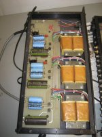
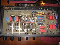
I will take some good close photos of the component sides of the boards. In the meanwhile here are a couple of not close enough images that are old. These were taken before going to the tech and don't show the janky diode work.
I will take some good close photos of the component sides of the boards. In the meanwhile here are a couple of not close enough images that are old. These were taken before going to the tech and don't show the janky diode work.
An externally hosted image should be here but it was not working when we last tested it.
An externally hosted image should be here but it was not working when we last tested it.
1 paralleling diodes is BAADDDD. They are not resistors and do not auto load balance.
2. for the hum, the easiest thing is to lift the heater voltage above ground. The cap is optional but recommended, or use 2 small mkv caps on both sides of the heater as steve does it.
http://i573.photobucket.com/albums/ss171/jonnyeye/filrefvoltage.gif
DCPP Amp
That's interesting about the diode thing. I wonder if that's the problem. There is no way this preamp hummed when it was new. The heater thing is a little beyond my knowledgebase and I am afraid I would blow everything up.
in the mean time of getting approved for audio karma dot org,
(it would have been better to directly upload pics on this forum)
Sometimes the power supply's magnetic field is induced into pcb runs, tube elements, and signal transformers (if used) especially if they are directly stacked.
Try spacing out the power supply chassis from the pre chassis to see if this is the case.
is this power supply a mod? If memory serves me right, it was all in one unit, the B+ was linear regulator as well as DC heaters with regulators. parallel diodes is bad call on his part. should use a 6A10 for a simple power diode. The stock pre from memory was two small bridge rectifiers located near the back-left of the pre amp.
Last edited:
Um 2 resistors is too diy for you? Ok put the multimeter on dc. While the unit is on measure from 1 heater to the high voltage lead of one of the tubes. Then measure from the high voltage lead of the tube to ground. If they are the same voltage then your heaters are not lifted above ground.
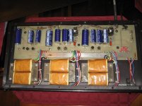
ok this is the newer one that is stock split chassis
the biggest change was the pots and thier linkage as they were plastic.
the grey caps in the preamp side need replacement.
these caps have a history of being cooked by the neighboring heat sink. Replace them with high temp caps.
remove the wima caps and install orange drop caps as wima caps are really low quality (regaurdless what others might want you to think. maybe because they are red who knows)
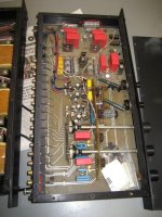
Here are the newest pictures.
You can see the janky diode work.
Also, why did he cut the resistor off of the balanced output? He said it increased the output of the preamp or something? I don't know what exactly he did that for.
Evan
You can see the janky diode work.
Also, why did he cut the resistor off of the balanced output? He said it increased the output of the preamp or something? I don't know what exactly he did that for.
Evan
Attachments
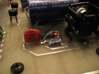
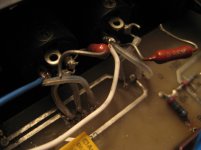
I would clean up the area around those diodes - and preferably replace them with one of the appropriate rating (as other point out). Clean up the board with some flux cleaner. If you don't have any, start with isopropyl alcohol (rubbing alcohol) on a cotton swab. If that doesn't clean the brown flux stuff off, use acetone (careful around plastic parts!!)
The purpose of flux is to clean the solder joint during the soldering process. Once, the parts are soldered on, there's no use for the flux. But it does tend to absorb water and cause electrical leakage issues that could result in hum.
It looks like the resistors on the XLR inputs connected one signal lead to GND through the resistor. The "tech" cut the resistors as he suspected a ground loop problem. Try connecting ONE of those resistors.
~Tom
Last edited:
Can do Tom. I think that diode situation needs to be rectified. I may actually have some appropriate ones here that I can use.
Read the type number on the diodes already there. Probably 1N.... Then we can figure out what a suitable replacement would be -- unless you have a schematic that shows what it's supposed to be.
~Tom
I would clean up the area around those diodes - and preferably replace them with one of the appropriate rating (as other point out). Clean up the board with some flux cleaner. If you don't have any, start with isopropyl alcohol (rubbing alcohol) on a cotton swab. If that doesn't clean the brown flux stuff off, use acetone (careful around plastic parts!!)
also, be sure if you get a white residue after cleaning, clean this as this is really conductive.
remove the blue twisted wire, and the white twisted wire as those I don't remember them being there.
0 ohm fusing resistor goes on pin1 to ground but can be left open (nothing on pin 1)
positive signal to pin 2
inverted signal to pin 3
Last edited:
remove the wima caps and install orange drop caps as wima caps are really low quality (regaurdless what others might want you to think. maybe because they are red who knows)
I'm not sure where you get that from. The Wima MKP are polypropylene caps. That's one of the lowest loss dielectrics and the one that contributes the least to distortion.
The hum is not caused by these caps. Fix the hum. Then upgrade to boutique caps if you have too much money burning holes in your pockets.
~Tom
12b2 is the diode number. I had to cut one out to read it... so I don't want to power it up until I get the proper diode installed.
The white and blue twisted wires are original (or were like that when I got the preamp), but not the same color as the factory installed wire. He replaced a length of wire that was too short with that. I can try disconnecting that after I get that diode swapped. I want to do one thing at a time so I know what I did if something crazy happens.
Thanks guys.
- Status
- This old topic is closed. If you want to reopen this topic, contact a moderator using the "Report Post" button.
- Home
- Amplifiers
- Tubes / Valves
- lazarus preamp hums even with volume down and no components connected.