After a long moment of reflection I´ve decide to offer layouting for nothing!
The only requirement is a interesting circuit or a mature design. I will offer a lot of experience and expertise but don´t request any development, they are generally long lasting and not free of charge.
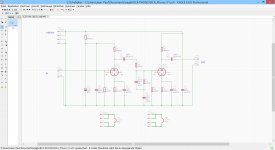
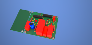
My tools are: EAGLE, SKETCHUP (with the necessary plugins).
I´m very curious about replies...
P.S.: I´m the coming week for business on the road
The only requirement is a interesting circuit or a mature design. I will offer a lot of experience and expertise but don´t request any development, they are generally long lasting and not free of charge.
My tools are: EAGLE, SKETCHUP (with the necessary plugins).
I´m very curious about replies...
P.S.: I´m the coming week for business on the road
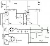
Please, can you design a pcb for this amp? is very interesting:
http://www.diyaudio.com/forums/chip...onductance-current-amplifier.html#post3564061
http://www.diyaudio.com/forums/chip...onductance-current-amplifier.html#post3564061
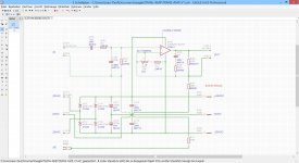
Yes, a cheap and very good amp.
In te original the common ground is in the two 4700uF, not in the two added 0,1uF.
Thanks a lot
In te original the common ground is in the two 4700uF, not in the two added 0,1uF.
Thanks a lot
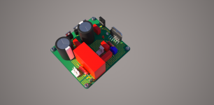
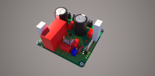
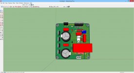
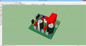
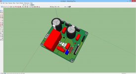
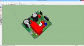
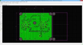
... here the printed board assembly, please check.
A version with MRA05 and MP930 and a version with SQM7 resistors...
A version with MRA05 and MP930 and a version with SQM7 resistors...
Attachments
-
 TRANS-AMP_High_Render.png714.3 KB · Views: 348
 -
 TRANS-AMP_Cheap_Render.png768.7 KB · Views: 305
 -
 TRANS-AMP_SKP4.jpg237.6 KB · Views: 278
 -
 TRANS-AMP_SKP3.jpg234.2 KB · Views: 874
 -
 TRANS-AMP_SKP2.jpg258.5 KB · Views: 907
 -
 TRANS-AMP_SKP1.jpg257.3 KB · Views: 943
 -
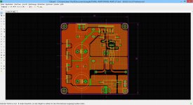 TRANS-AMP_BRD.jpg750.7 KB · Views: 1,001
Impressive! Really a great job. But, please, can be single sided?
If not, please, post the drawing of the pcb.
Thanks again.
If not, please, post the drawing of the pcb.
Thanks again.
... here the printed board assembly, please check.
A version with MRA05 and MP930 and a version with SQM7 resistors...
Could you post this/these to Dirt Cheap Dirty Boards ? Given OK from any circuit tm, (r) or (c) issues?
//
I would be tempted to use smaller pitch 0.1uf caps and move them nearer the device...
and the 0.1 μF supply decoupling capacitors as close as possible to the
LM3875 to reduce the effects of PCB
Wouldn't it be better to move the parts that are intended to be mounted to a heatsink more to the board edge?
... please check.
Do you intend to build this amplifier?
I am very impressed from what I have seen.
-
may I suggest to put a 1MOhm resistor from output to ground, just to make sure that output cap is properly charged.... if you turn this one on as is, and plug your line stage, it might blow the input transistors.....
Hello jps1964.
If you design more layouts, please, can be preferred single sided? So can be hand made in house, best for DIY, I think. The doble layer need to be order to a PCB company.
I have forget say this in my first post, and if you made other interesting layouts is more easy (and cheap) for all of us translate to the reality. All in all, this is a DIY Forum.
Thanks again for your (very) good work.
- Status
- Not open for further replies.
- Home
- Design & Build
- Software Tools
- Layouting for free