Hi all,
I was given this amplifier by the local car audio shop after they "had a go at fixing it"...
It's in a sorry state, the speaker terminals were broken off and replaced with wire, a rail cap had been replaced with one of the same specs but of a completely different shape that was hot glued to the case, mismatched output stage mosfets and almost every other repair faux pas including what I think was an ancient joint roach rattling around inside...😀😀
Anyway, of the output mosfets IR FB3120D two read a dead short between all three terminals, 10 identified as single diodes on the transistor tester, one as a IGBT and only one as a MOSFET. I am not sure if the output section went because two mismatched ( from another batch ) FB3120D mosfets were used at the last repair (incidentally the only two that tested as mosfets as mentioned above) or whether they are a weakness in this amplifer?
If it is the latter I would be grateful if anyone could suggest up-rated replacements as I'm replacing them all anyway?
The power supply has one bank of five mosfets reading short, looking at the back of the board it appears to have been a slip with a probe judging by the little electrical scorch mark on the between the Gate and Source of one of them. They are IRFZ46N for reference and I would like to know if I am ok replacing just that bank or whether I should renew the lot, in the case of the latter suggestions for possible upgrades would be gratefully considered?
Finally there are some big diodes D301, D302, D303 that seem to read as conductive both directions,I am guessing from this that the amp was connected with a reverse polarity at least once in it's lifetime. Can I remove these and power up the amp ( with the rectifier removed) to test the power supply section?
( please ntoe that Schematic provided is for a Rev B. of the amplifier, I have a Rev B amplifer which appears to use some different components in a few places, the output mosfets being an example)
Attachments
Hi all,
I was given this amplifier by the local car audio shop after they "had a go at fixing it"...
It's in a sorry state, the speaker terminals were broken off and replaced with wire, a rail cap had been replaced with one of the same specs but of a completely different shape that was hot glued to the case, mismatched output stage mosfets and almost every other repair faux pas including what I think was an ancient joint roach rattling around inside...😀😀
Anyway, of the output mosfets IR FB3120D two read a dead short between all three terminals, 10 identified as single diodes on the transistor tester, one as a IGBT and only one as a MOSFET. I am not sure if the output section went because two mismatched ( from another batch ) FB3120D mosfets were used at the last repair (incidentally the only two that tested as mosfets as mentioned above) or whether they are a weakness in this amplifer?
If it is the latter I would be grateful if anyone could suggest up-rated replacements as I'm replacing them all anyway?
The power supply has one bank of five mosfets reading short, looking at the back of the board it appears to have been a slip with a probe judging by the little electrical scorch mark on the between the Gate and Source of one of them. They are IRFZ46N for reference and I would like to know if I am ok replacing just that bank or whether I should renew the lot, in the case of the latter suggestions for possible upgrades would be gratefully considered?
Finally there are some big diodes D301, D302, D303 that seem to read as conductive both directions,I am guessing from this that the amp was connected with a reverse polarity at least once in it's lifetime. Can I remove these and power up the amp ( with the rectifier removed) to test the power supply section?
( please ntoe that Schematic provided is for a Rev B. of the amplifier, I have a Rev B amplifer which appears to use some different components in a few places, the output mosfets being an example)
Hi, these amps are very famous for their ineffective protection systems.
They have many defects, and the most serious, concern the overheating of some critical components.
Unfortunately, if you found short output mosfets, at 90% the power supply was damaged.
In my life, I have repaired at least 15 opti2000 and only 2 of these have had the power supply intact after a short on the output mosfets, the others have destroyed all the mosfets because the protection does not intervene promptly.
The three large diodes serve to reverse the polarity on the power cables and remove them, you can do all the tests you want, but you can no longer make mistakes with polarity reversal.
Remove the 4 power diodes and turn on the amplifier, but remember that all other regulated power sources do not use those 4 diodes, which is why if there is something short you could do damage.
Hi Mario,
Yes it seems like a bit of a janky amp, the little fan that cooled the Class D driver board was almost dead, the whole idea with all those driver transistors stacked hard up against each other seems like particularly bad design.
I have found two suspect driver transistors on the power supply side (Q312 &Q313) but these do not drive the defective power supply mosfets, the drivers for the blown mosfets seems fine...😕
I've temporarily replaced the blown MOSFETS with some I had on hand, The amp tries to power up ( and doesn't blow a 20 amp fuse) but the protection circuit kicks in preventing it from powering up. This is with the outputs and rectifiers out of the circuit.
I suspect the diodes of shorting to ground and so was wondering if I could remove them without damaging anything further.
I shall remove them and order new ones to see if that takes it out of protection if that is safe?
Hi Mario,
I have found two suspect driver transistors on the power supply side (Q312 &Q313) but these do not drive the defective power supply mosfets, the drivers for the blown mosfets seems fine...😕
When you find even one broken driver transistor, it's best to change them all, even those of the other transformer.
If memory doesn't deceive me, the driver transistors usually used in this amplifier are the KEC KTA1023 and KEC KTC1027, which can be replaced with the BD139 and BD140 because these are better and pinout compatible.
Check all gate resistors (which should be 100ohm).
I've temporarily replaced the blown MOSFETS with some I had on hand, The amp tries to power up ( and doesn't blow a 20 amp fuse) but the protection circuit kicks in preventing it from powering up. This is with the outputs and rectifiers out of the circuit.
What kind of mosfet are you using for the tests?
Did you fix the drivers of these mosfets?
If yes, it is very strange that the amplifier continues to stay in protection even without power diodes and output mosfets.
The driver board may also need to be removed.
Since the amp was in bad shape in all aspects, your goal is to first make the power supply work, then switch to the amplifier, so better remove everything that may have been damaged during the last failure (mosfet of audio + driver card).
I suspect the diodes of shorting to ground and so was wondering if I could remove them without damaging anything further.
I shall remove them and order new ones to see if that takes it out of protection
What diodes are you referring to?
POLARITY REVERSAL or power diodes?
It is generally very easy to repair these amplifiers, but you have to take into consideration that there are many components that can be easily broken with a failure, for example, the gate resistors (both of the power supply and of the audio) may seem ok, but in reality may be interrupted or out of tolerance.
In the amplifier, on the gates, there are diodes in parallel with the gate resistor that can break and be seen as a short circuit and the only way to test it is removing from the board because is in parallele with the low value gate resistors that can distort the test.
Finally there are some transistors on the driver card that can break, indeed, almost certainly after the failure they broke.
Last edited:
Do a forum search for Q124 Q125. If the audio driver board uses that numbering configuration, those drivers are likely defective, even if they check OK with a meter.
I use the IRF3205 in the power supply with 47 ohm gate resistors. All of the PS drivers get replaced with the BD139 and BD140. Install the drivers so that they stand well off of the board and solder from both sides.
The protection circuit threshold setting resistor can be lowered to make the protection circuit more effective. Doing that AND using the 3205 will generally let the supply survive if the outputs fail.
do NOT use IRFB31N20Ds from any source that isn't authorized by the manufacturer. If you buy them from ebay, EXPECT to get counterfeit parts. There is no upgrade on the outputs. Like most all class D amps, the output stage is very sensitive to changes and even if the 'upgraded' parts seem the work, they're unlikely to be reliable. There may be subs but it would require the adjustment of circuit board component values and a LOT of testing (many hours, different temps, conditions, loads...) to determine if they're really better than the originals.
When you find even one broken driver transistor, it's best to change them all, even those of the other transformer.
If memory doesn't deceive me, the driver transistors usually used in this amplifier are the KEC KTA1023 and KEC KTC1027, which can be replaced with the BD139 and BD140 because these are better and pinout compatible.
Check all gate resistors (which should be 100ohm).
I will check them all as the drive signal to the bank of MOSFETS Q420-Q424 is weird.
What kind of mosfet are you using for the tests?
Did you fix the drivers of these mosfets?
I simply removed all the MOSFETS from the bank where one had blown as I couldn't tell in circuit whether one or all five had blown. I was wondering if it was worth using upgraded mosfets and replacing them all?
If yes, it is very strange that the amplifier continues to stay in protection even without power diodes and output mosfets.
The driver board may also need to be removed.
Since the amp was in bad shape in all aspects, your goal is to first make the power supply work, then switch to the amplifier, so better remove everything that may have been damaged during the last failure (mosfet of audio + driver card).
What diodes are you referring to?
POLARITY REVERSAL or power diodes?
The amp comes out protect and draws around 1.3 amps with the faulty bank of MOSFET's removed and the power diode rectifiers removed. It appeas that the reverse polarity diodes I mentioned do not put the amp into protection but I am suspicious of them and want to pull them to test out of circuit. It does occur to me that if they were fault they would be short and draw more current but I can't be sure without checking.
It is generally very easy to repair these amplifiers, but you have to take into consideration that there are many components that can be easily broken with a failure, for example, the gate resistors (both of the power supply and of the audio) may seem ok, but in reality may be interrupted or out of tolerance.
In the amplifier, on the gates, there are diodes in parallel with the gate resistor that can break and be seen as a short circuit and the only way to test it is removing from the board because is in parallele with the low value gate resistors that can distort the test.
Finally there are some transistors on the driver card that can break, indeed, almost certainly after the failure they broke.
Thanks Mario, some of those tiny diodes are visibly damaged and I was going to check them once I have the PSU up and running.
thanks for all your help! 🙂
Do a forum search for Q124 Q125. If the audio driver board uses that numbering configuration, those drivers are likely defective, even if they check OK with a meter.
I use the IRF3205 in the power supply with 47 ohm gate resistors. All of the PS drivers get replaced with the BD139 and BD140. Install the drivers so that they stand well off of the board and solder from both sides.
The protection circuit threshold setting resistor can be lowered to make the protection circuit more effective. Doing that AND using the 3205 will generally let the supply survive if the outputs fail.
do NOT use IRFB31N20Ds from any source that isn't authorized by the manufacturer. If you buy them from ebay, EXPECT to get counterfeit parts. There is no upgrade on the outputs. Like most all class D amps, the output stage is very sensitive to changes and even if the 'upgraded' parts seem the work, they're unlikely to be reliable. There may be subs but it would require the adjustment of circuit board component values and a LOT of testing (many hours, different temps, conditions, loads...) to determine if they're really better than the originals.
Brilliant, thank you Perry. 🙂
I tested the removed IRFZ46Ns in the transistor checker and only one is blown, with the rest re-installed in the board it powers up and the protection LED extinguishes after a few seconds.
It is producing rail voltage at the rectifier pads but exhibits terrible ringing, to the extent that the transformers and mosfets become warm after a few minutes of power up.
Tracing the drive signals back to the 3525A PWM controller and found that both the sawtooth wave on pin 5 and the square waves on pins 11 &14 exhibited ringing.
Is this a sign of a failing IC or could downstream components be causing it?
It could be Perry, I'm grounding on the Ground terminal block with a short probe lead though.
Is there some way I could check whether it is the ground or not, I've tried taking a measurement without the scope ground connected at all ( oscilloscope not isolated ) and with an there was no difference in the waveform.
Is there some way I could check whether it is the ground or not, I've tried taking a measurement without the scope ground connected at all ( oscilloscope not isolated ) and with an there was no difference in the waveform.
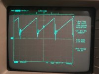
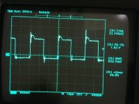
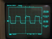
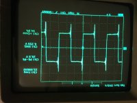
The first image is the output from pin 5 of the IC.
The second image is the output from pins 11 & 14.
The third image is the from the leg of the MOSFET.
The fourth image is from the rectifier pad.
The second image is the output from pins 11 & 14.
The third image is the from the leg of the MOSFET.
The fourth image is from the rectifier pad.
Attachments
What's the resistance from the tip of the ground probe to the body of the scope?
Reads as zero Ohms from the ground probe crocodile clip to the first chassis screw on the side of the scope.
Does it get better if you switch the probe from 10x to 1x?
What if you ground to the source pad for the FET and touch the gate pad?
What if you ground to the source pad for the FET and touch the gate pad?
It doesn't appear to, I will try the Scopemeter tomorrow to check it though.
Thanks for your help as always.
Thanks for your help as always.
In my humble opinion, those waveforms are too normal.
Consider that this type of amplifier does not enjoy excellent cleaning and shielding, and sometimes even the transformers themselves, when they oscillate at high frequencies, radiate high-frequency noise in the surrounding area that can "disturb" your oscilloscope.
If I were you, I would replace all power mosfets with IRF3205 with 47 ohm r-gate and I would replace all drivers, even if they are ok.
The old ones might be enough, but since the irf3205 are a bit heavier to drive, a more robust driver could be a must.
The whistle of the transformers may be due to the defective drivers.
SG3525 hardly breaks, but it is not impossible.
Your signals, however, seem to me OK.
Does it get better if you switch the probe from 10x to 1x?
What if you ground to the source pad for the FET and touch the gate pad?
So checking again with the Scopemeter on battery power, the signals seem identical to those above.
The drive wave at the gate isn't too bad, as per the image above, but the result coming out of the mosfet exhibits the ringing.
In my humble opinion, those waveforms are too normal.
Consider that this type of amplifier does not enjoy excellent cleaning and shielding, and sometimes even the transformers themselves, when they oscillate at high frequencies, radiate high-frequency noise in the surrounding area that can "disturb" your oscilloscope.
If I were you, I would replace all power mosfets with IRF3205 with 47 ohm r-gate and I would replace all drivers, even if they are ok.
The old ones might be enough, but since the irf3205 are a bit heavier to drive, a more robust driver could be a must.
The whistle of the transformers may be due to the defective drivers.
SG3525 hardly breaks, but it is not impossible.
Your signals, however, seem to me OK.
Thanks for your thoughts Mario, much obliged.
I have ordered some IRF3205 to refresh the power supply mosfets with and some 47 ohm resistors. I hope that 1% tolerance is good enough here?
I tried again with my isolated 'scope, which is a battery powered Fluke 105B, it gave identical results to that of the bench scope, I hear what you say about the amp being a noisy design.
I think part of the problem with these amps is that they are advertised as being half ohm stable and the sort of people attracted by that sort of advertisement will probably work these amps very hard as a consequence.
I took this on as a learning exercise and with no commercial considerations for something like this reason myself, hence wondering about upgrades, as I have a JL Audio 13w7 with dual 1.5 ohm voice coils.
This sub is rated at around 1000-1500 W continuous but what interests me more is that the company's home cinema flagship subwoofer uses two of these subs and around 3000 W RMS for the amplifier. This indicates to me that the sub is good for big transient bursts ( suits the sort of music I listen to) and so I want 2000W + to experiment with.
This is an issue as very few amps can supply that sort of power at 3 Ohms, with the voice coils wired in series, and also very few reliably at 0.75 Ohms, with the coils wired in parallel.
My idea then was to try this amp at 0.75 Ohms, if it was indeed 0.5 Ohm stable it should take it and deliver about 500-600 watts more than my current "big amp", a JBL GTO14001.
However it seems that everyone is telling me this amp is crap even when working... 😀
Ok, so now that the power supply is up and running ( minus the blown mosfet in one of the banks) am I ok to re fit the rectifiers and power up the amplifier section whilst waiting for the replacement components to arrive?
It may seem strange, but maybe the JBL amplifier is better.
OPTI2000 can work at 0.5 ohm and maybe it will give more power, but not so much compared to the Jbl.
OPTI2000 can work at 0.5 ohm and maybe it will give more power, but not so much compared to the Jbl.
- Home
- General Interest
- Car Audio
- Lanzar Optidrive 2000D