I quite agree Mario, it is in all probability a better and more powerful amplifier but I enjoy experimenting and being able to have the data. Hopefully the upgraded power supply MOSFETs will help with the low impedance load. 🙂
I got this amp for nothing, if nothing else I'll add it to the "small" collection of amplifiers I have. You should know, when I was focused on vintage Hifi I managed to acquire 14 vintage receivers before the domestic situation became too difficult! 😀
I lifted the legs of those output diodes, they test fine thankfully.
I reinstalled the rectifiers and powered it up, it doesn't go into protection.
There are however issues.
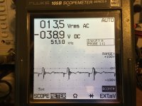
The waveform of the DC coming from the rectifier doesn't look very nice at all. (first picture)
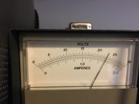
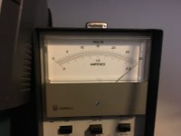
The second is that sometimes it starts up and draws 1.3 amps at idle and other times it starts up draws up to the 2 amp limit of the supply.
Wiggling components doesn't seem to make it go from one state to another.
There are however issues.
The waveform of the DC coming from the rectifier doesn't look very nice at all. (first picture)
The second is that sometimes it starts up and draws 1.3 amps at idle and other times it starts up draws up to the 2 amp limit of the supply.
Wiggling components doesn't seem to make it go from one state to another.
Attachments
The amp will idle at slightly less current if the output stage hasn't yet started to oscillate and sometimes it takes a bit of encouragement via an input signal to make it start oscillating.
Thanks Perry, this is more of an intermittent thing, sometimes it idles happily at ~1.5 amps and at others it draws as much as the supply will put out with seemingly little difference between the two in terms of voltages taken around the amp.😕
I'm getting rail voltage of ~ +-75 volts on the output section MOSFETS, it looks much smoother on the output side than it did on the PS side! 😱
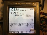
I'm not getting much in terms of drive signal, I i understand correctly I am expecting a high frequency square wave of varying duty cycle, instead I'm getting all sorts of rubbish.
Moving the transistors on the driver board change the shape of the random waveforms I'm getting and so I think your advice to replace every transistor on that board anyway is the way forward here rather than fault finding.
I did that search you suggested, much good information there also.
I'm getting rail voltage of ~ +-75 volts on the output section MOSFETS, it looks much smoother on the output side than it did on the PS side! 😱
I'm not getting much in terms of drive signal, I i understand correctly I am expecting a high frequency square wave of varying duty cycle, instead I'm getting all sorts of rubbish.
Moving the transistors on the driver board change the shape of the random waveforms I'm getting and so I think your advice to replace every transistor on that board anyway is the way forward here rather than fault finding.
I did that search you suggested, much good information there also.
Are you saying that you're not getting a rail-rail oscillation on the output transistors when driving a signal into the amp?
Others may have had other experience but Q124 and Q125 are the only transistors that commonly fail. I repaired literally hundreds of this type amp and they have a lot of issues but the driver board typically has problems with those 2 transistors.
Do you have a larger supply with a current limiting resistor? That would likely be better than a 2 amp supply.
Assuming I understand rail-to-rail oscillation, no I don't.
I also seem to be missing the schematic for the driver board, is Q125 and Q124 on that?
I think the driver board is completely kaput as I don't have any drive signal to the low side at all and the drive signal to the high side is all over the place but seems trying to produce a pulse of some sort. The voltages on the legs of the transistors on the driver board also read all over the place, from 30-90 volts.
I am assuming it's probably best to replace the lot?
I do, I have a supply that can do about 60 amps and some 25W resistors at 1, 4 and 8 ohms.
Success!
I found a dry solder joint on the back of the driver board, it was covered by some black gloop until I removed it, soldering it up and driving a signal into the amp at startup results in a drive wave on the gate pads of the output MOSFETs.
EDIT: Only the High Side has drive, the low side shows rail voltage - 7 v where the drive wave ought to be...
Last edited:
I've taken the driver board out and checked it over. The capacitors were 85C rated ones from "Kelna" and were quite bulged so I replaced them with low ESR 105C jobs.
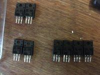
I pulled and tested the transistors but very stupidly didn't write down or take a photo of where the KA1837 and C4793 transistors go, ~I have ordered BD139 and BD 140 replacements but does anyone have a schematic for this driver please?
It's Part Number is R200602002.
I pulled and tested the transistors but very stupidly didn't write down or take a photo of where the KA1837 and C4793 transistors go, ~I have ordered BD139 and BD 140 replacements but does anyone have a schematic for this driver please?
It's Part Number is R200602002.
The BD transistors are for the PS only, just to be clear.
There were multiple boards, post a photo of the actual driver board in your amp.
Which caps were bulged?
There were multiple boards, post a photo of the actual driver board in your amp.
Which caps were bulged?
Hi Perry,
Apologies, I should have realised there would be multiple revisions of the board.
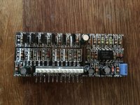
The board I have is as per the first photograph.As you predicted Q125 and Q 124 (KA1837 I think) tested weirdly as compared to Q126 and Q127 on the transistor tester, showing about half the Hfe whereas the four KC4793 transistors seemed very well matched.
Q112 was dead, I have removed it and am trying to find a replacement.
The small transistors Q110-Q1114, Q116,Q118 and Q110 were running extremely hot before I took the drive board out.
I am minded to replace the lot but it seems the 2SC3228 transistor of Q112 is hard to get hold of?
Should I replace them all and are there any easy to get hold of substitutions or upgrades that don't run so hot?
The bulged caps were C150 and C151, I have a box of capacitors and the spares tested better than the old ones which showed high leakage current and ESR.
Apologies, I should have realised there would be multiple revisions of the board.
The board I have is as per the first photograph.As you predicted Q125 and Q 124 (KA1837 I think) tested weirdly as compared to Q126 and Q127 on the transistor tester, showing about half the Hfe whereas the four KC4793 transistors seemed very well matched.
Q112 was dead, I have removed it and am trying to find a replacement.
The small transistors Q110-Q1114, Q116,Q118 and Q110 were running extremely hot before I took the drive board out.
I am minded to replace the lot but it seems the 2SC3228 transistor of Q112 is hard to get hold of?
Should I replace them all and are there any easy to get hold of substitutions or upgrades that don't run so hot?
The bulged caps were C150 and C151, I have a box of capacitors and the spares tested better than the old ones which showed high leakage current and ESR.
Attachments
Last edited:
I don't remember seeing any of the large drivers fail but they do get bad connections.
Is Q112 in parallel with Q118?
Is Q112 in parallel with Q118?
I don't think so, it seems to drive Q110 and Q111, which are in parallel.
Attachments
Last edited:
They appeared to rearrange the components in this version. It appears that the base of Q112 goes to the Zener D114. If so, it's not a critical part. Something like the KSC2690A should be a good sub.
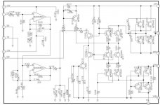
See attached.The components are different but the circuit is similar.
See attached.The components are different but the circuit is similar.
Attachments
Thanks Perry, that's very helpful.
In assume there is no need to change the smaller transistors for higher dissipation capable parts after Q112 has been replaced?
In assume there is no need to change the smaller transistors for higher dissipation capable parts after Q112 has been replaced?
If you do anything to get the parts to operate cooler, make sure the fan is working properly. You can also install (identical) new parts with long legs so the parts are closer to the fan. Clip-on heatsinks with heatsink compound can also be used.
Was the fan blowing towards the board or towards the inductors?
Was the fan blowing towards the board or towards the inductors?
The fan was really on its last legs and blowing feebly towards the board.
I understand the original is a 40x40x10mm 5.6 cfm type, I have found a 40x40x20mm 6,5 cfm type that I think will fit and will place the fan closer to the board.
I understand the original is a 40x40x10mm 5.6 cfm type, I have found a 40x40x20mm 6,5 cfm type that I think will fit and will place the fan closer to the board.
The Sunon ME40101VX-000U-A99 is about 10CFM and the same size.
The fans are generally salvageable if you disassemble them and relube the bushing.
The fans are generally salvageable if you disassemble them and relube the bushing.
Were you able to find the transistor positioning order?Hi Perry,
Apologies, I should have realised there would be multiple revisions of the board.
The board I have is as per the first photograph.As you predicted Q125 and Q 124 (KA1837 I think) tested weirdly as compared to Q126 and Q127 on the transistor tester, showing about half the Hfe whereas the four KC4793 transistors seemed very well matched.
Q112 was dead, I have removed it and am trying to find a replacement.
The small transistors Q110-Q1114, Q116,Q118 and Q110 were running extremely hot before I took the drive board out.
I am minded to replace the lot but it seems the 2SC3228 transistor of Q112 is hard to get hold of?
Should I replace them all and are there any easy to get hold of substitutions or upgrades that don't run so hot?
The bulged caps were C150 and C151, I have a box of capacitors and the spares tested better than the old ones which showed high leakage current and ESR.
If you have problems, I have a complete and functioning driver board in the laboratory (identical to yours), so if you need it I can help you.
I think I have the right order given the schematic Perry kindly posted above, I basically substituted the transistors on there with the transistors I have on the basis of NPN for NPN and visa versa with the transistors I had.
thank you for your offer, its very much appreciated and I may be bothering you for it my own effort ends in clouds of smoke... 😀
I have ordered two transistors to replace Q124 and Q125 as advised.
thank you for your offer, its very much appreciated and I may be bothering you for it my own effort ends in clouds of smoke... 😀
I have ordered two transistors to replace Q124 and Q125 as advised.
The power supply mosfets have arrived but are IRF3205z rather than IRFZ3205.
Looking at the data sheet it seems that only difference is a slightly lower adds for the former?
Are they ok or should I send them back and get the latter?
Looking at the data sheet it seems that only difference is a slightly lower adds for the former?
Are they ok or should I send them back and get the latter?
- Home
- General Interest
- Car Audio
- Lanzar Optidrive 2000D