If i remove the TIP31C and TIP 32C and the A970 and C2229 heres what i get on the pads for the drivers..
TIP31C
Leg 1:-0.21
Leg 2:52.9
Leg 3:0.00
TIP32C
Leg 1:-0.21
Leg 2:-53.3
Leg 3:0.00
If i re-install the C2229 i get the 53 volts on all 3 legs back..
Is there a good sub for thoose ??
I have some C2235's on hand would thoose be a good replacement or no?
TIP31C
Leg 1:-0.21
Leg 2:52.9
Leg 3:0.00
TIP32C
Leg 1:-0.21
Leg 2:-53.3
Leg 3:0.00
If i re-install the C2229 i get the 53 volts on all 3 legs back..
Is there a good sub for thoose ??
I have some C2235's on hand would thoose be a good replacement or no?
On the working channel, do you read 0 ohms between the center legs of the outputs and the adjacent drivers?
Look for a bad solder connection on the PNP output transistor. It may be a jumper feeding the outputs.
If i remove all of the outputs and drivers from the right channel the 51 volts remains..
If i remove the C2229 the voltage is gone..
So i guess i will go touch up all of the solder connections in that channel and test the transistors..
If i do find that the C3229 is defective is there a good sub for it ??
The collector of the C2229 connects to the base of the TIP32C
If i remove the C2229 the voltage is gone..
So i guess i will go touch up all of the solder connections in that channel and test the transistors..
If i do find that the C3229 is defective is there a good sub for it ??
The collector of the C2229 connects to the base of the TIP32C
You cannot have a loss of negative rail on the center leg of the transistors (PNP outputs and drivers) unless there is a bad connection to the negative rail. I'm assuming that this is a standard Asian design that takes the output from the emitters of the outputs.
I have the outputs and Drivers roved from the right channel..
I reflowed all the solder connections in the right channel..
Heres what i get on the pads for the Tip 31c,32c
TIP31C
Base:-53.2
Collector:52.9
Emitter:0.00
TIP32C
Base:-53.2
Collector:-53.3
Emitter:0.00
Theese voltages still dont look right to me any thoughts?
I reflowed all the solder connections in the right channel..
Heres what i get on the pads for the Tip 31c,32c
TIP31C
Base:-53.2
Collector:52.9
Emitter:0.00
TIP32C
Base:-53.2
Collector:-53.3
Emitter:0.00
Theese voltages still dont look right to me any thoughts?
You cannot rely on voltage within the feedback loop when the loop is open (which it is with no outputs in the circuit).
Reinstall the outputs.
Reinstall the outputs.
With all the outputs and drivers installed in the right channel heres what i get..
TIP31C
Base:-53.3
Collector:52.9
Emitter:-52.6
TIP32C
Base:-53.0
Collector:-53.1
Emitter:-52.6
TIP31C
Base:-53.3
Collector:52.9
Emitter:-52.6
TIP32C
Base:-53.0
Collector:-53.1
Emitter:-52.6
Have you removed and checked all of the transistors in the channel for leakage and open junctions as well as shorts?
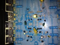
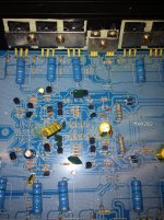
Post a good quality photo of the defective channel where all of the circuit board designations are legible.
heres a pic of the board..
If i remove transistor Q114 (red arrow pointin to it) The voltages will go back to normal on the drivers in the right channel and it will play clean audio but the audio is muted..
I replaced it with a new one and the voltage comes back..
If i remove transistor Q114 (red arrow pointin to it) The voltages will go back to normal on the drivers in the right channel and it will play clean audio but the audio is muted..
I replaced it with a new one and the voltage comes back..
Attachments
Last edited:
Remove the transistor just below the circuit board designation R224 in the photo. Does that eliminate the DC on that jumper?
- Status
- Not open for further replies.
- Home
- General Interest
- Car Audio
- Lanzar MXA 282