Ha, ha tell your wife she guessed the situation right, I will come in the night.......
How can a man with such a light name like "tea-bag" choose such a heavy solution more appropriate to diyaudio fellows with name like " War Hammer" or "Copper Woolf"
Best 😀
How can a man with such a light name like "tea-bag" choose such a heavy solution more appropriate to diyaudio fellows with name like " War Hammer" or "Copper Woolf"
Best 😀
Could you give an ETA for your preamp article?
Time really flies this time of year. I'll try to get it done over Thanksgiving and Christmas, then it's up to the publisher (which I don't have yet 🙂)
I have a second article about something else which I'll try to post on my blog before the end of the year.
I have the prototype PCBs, but I'll be making a couple of minor revisions. I wouldn't worry about the gain devices vanishing between now and then.
@Tea-Bag
I'm looking forward to hearing how your amps sound with those Lowthers. Are you using open baffles or cabinets?
Hello guys,
very interesting thread so far.
I am just wondering how do high voltage curves of 2sk82 look like,
this device has stated max Vd 240V. So if we have good looking curves in
higher region this could be an SET imagination... Has someone looked to this area?
very interesting thread so far.
I am just wondering how do high voltage curves of 2sk82 look like,
this device has stated max Vd 240V. So if we have good looking curves in
higher region this could be an SET imagination... Has someone looked to this area?
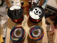
Any comments on my layout?
I am worried the Power transformers and Inductors are going to hum this close.
If you can see the signal board will mount way toward the back to keep signal path small as possible. The Heatsink and SITS will mount of the top of the unit towards the back.
Tested the signal board and inductor out. Works like a champ on two diffent Sony SITs and each channel of Signal board. Just concerned about layout before drilling in place.
Attachments
Hum was a non-issue for me at roughly the same distance. I wonder if you'll get some magnetic coupling between those inductors, though. I built monoblocks. I always build monoblocks.
ma
Maybe. In crossovers, the interaction is reduced by placing them perpendicular to each other.
Inductor Placement *PIC*
I wonder if you'll get some magnetic coupling between those inductors
Maybe. In crossovers, the interaction is reduced by placing them perpendicular to each other.
Inductor Placement *PIC*
Has someone looked to this area?
I have, and it's possible. 🙂
P.S. That's all I have to say about it right now. You may want to check out the most recent issue of Linear Audio for an article about the PASS-SIT-1 used under similar conditions.
Last edited:
I have, and it's possible. 🙂
P.S. That's all I have to say about it right now. You may want to check out the most recent issue of Linear Audio for an article about the PASS-SIT-1 used under similar conditions.
But if there was an SIT1 used this wont help me. The sony 2SK82 is different.
I know that its possible to use it in this way but the main question is how?
Its also obvious that you need an output transformer. In my opinion whit primary impedance from 150-300 ohms.
P.S. You could send me only this article if you have this issue (volume 4) and I can pay you for just that, I dont need the whole book.
Linear Audio is not my magazine, and I didn't write the article.
You can buy issues here: www.linearaudio.net
You can buy issues here: www.linearaudio.net
Linear Audio is not my magazine, and I didn't write the article.
You can buy issues here: www.linearaudio.net - home
So I see.
But could you not tell us more about your experince in this area of curves?
Did you use an output transformer ?
Thanks.
My experience is that there are some nice curves to look at.
Zen Mod gave you a link to the curves you're looking for, and I gave you a reference to an article that explains how to design a transformer-coupled SIT amp. Additionally, you may wish to read through one of the classic tube references, such as The Radiotron Designer's Handbook. Everything you need to is there.
Short of designing one, building it, writing a step-by-step article, and posting a schematic, I'm not sure what more we can do.
😕 something i don't understand here , if we make a Sit amp is to have a 'tube sound' without the weaknesss to use an output transformer ( limited bandwitch and distortions , and expensive price for a good one)..
- Home
- Amplifiers
- Pass Labs
- L'Amp: A simple SIT Amp