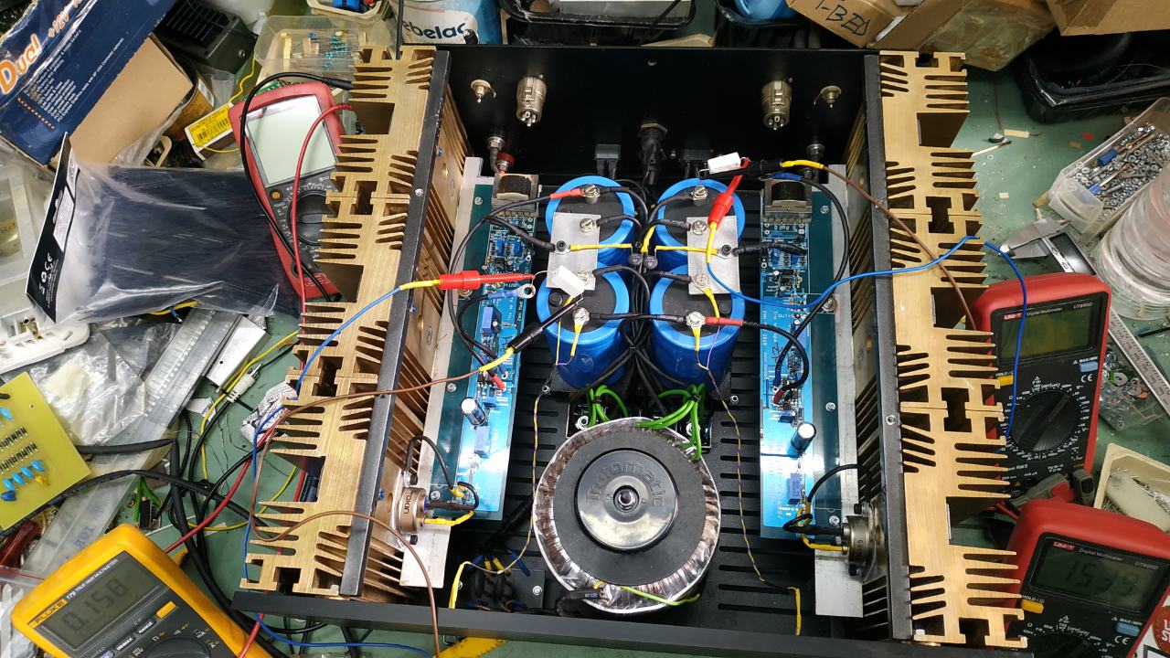
Okay, so I reworked the bias supply and changed the grounding scheme a tiny bit. Input ground, bias ground and the VFET's source ground-connection now meet at the VFET and go to the respective star ground from there.
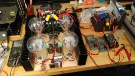
With the inputs individually shorted to ground I get zero hum through headphones (HD800, with 10R in parallel) connected to the output. As soon as I leave the inputs open or connect a source, there's audible hum. I'm kinda running out of ideas.
The output ground is connected to the star ground. Should I route it to the VFET (source) and ground it to the star ground from there? But if that connection is what's causing the hum, why does shorting the units silence the amp?
Attachments

Ground loop. Have you read this before? This article helped me to understand about grounding a lot.
Audio Component Grounding and Interconnection
Audio Component Grounding and Interconnection
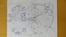
Oh boy, here we go. This is a sketch I drew up before starting with the build. It's surprisingly accurate, albeit ugly.
Edit: I must be getting close. Like I said, with the inputs shorted they're sub-mV noise. It must be the grounding.
Edit: I must be getting close. Like I said, with the inputs shorted they're sub-mV noise. It must be the grounding.
Attachments
Last edited:

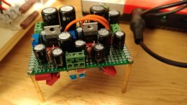
If I'm reading the pcb correctly, POS and NEG is the input side, and B+ and B- are the outputs. The ground plane is slotted to route the ground currents in a start-ground fashion.
My amp build quite visibly has a star ground too (which is not working 100% it seems). What am I missing?
My amp build quite visibly has a star ground too (which is not working 100% it seems). What am I missing?
Looking at your diagram in post #3084 and looking at ZM's board, your star is at the input side instead of the output side.
Your star is also not centred between the left and right sides.
Your star is also not centred between the left and right sides.
If I'm reading the pcb correctly, POS and NEG is the input side, and B+ and B- are the outputs. The ground plane is slotted to route the ground currents in a start-ground fashion.
My amp build quite visibly has a star ground too (which is not working 100% it seems). What am I missing?
no Bubba
Pos. GND and Neg are side to load
other side is side leading from diode bridges
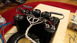
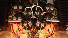
Okay, I thought that the first cap as seen from the rectifier is the lowest impedance point of the PSU and is thus used as the start-ground location. Guess I'll move the star-ground point to the ones furthest away and see what happens. Should be easy enough with the screw terminals and all.
your GND take out ( leading to load) point must be equidistant to terminals of these two central caps , and also need to be mounted not in area of greatest pulsating currents
one Al plate would do the job - with 3 holes ; two holes for caps terminals , one hole for GND take out point
these 3 holes pretty much forming a triangle
see enclosed
one Al plate would do the job - with 3 holes ; two holes for caps terminals , one hole for GND take out point
these 3 holes pretty much forming a triangle
see enclosed
Okay, so here's the revised grounding scheme.
Edit: If this works, I think I'll be getting this on a T-shirt.
Edit: If this works, I think I'll be getting this on a T-shirt.
Attachments

Last edited:
that could work
if some buzz persists , try fat wire bridge between two channel main GNDs , meaning , fat wire tying two sources directly
if some buzz persists , try fat wire bridge between two channel main GNDs , meaning , fat wire tying two sources directly
Aight, I rerouted the amp's ground connections and fired it up again. Sub-mV noise with a source connected, just barely audible through the HD800. On most classical records the background noise is above that...
I'm not sure if I can get it any more quiet.
Time to vectorize that t-shirt print.
I'm not sure if I can get it any more quiet.
Time to vectorize that t-shirt print.
Attachments
Oh, and I forgot to add...
Mighty Zen Mod saved the day!
Having the star ground at the PSU output side really was news to me.
Mighty Zen Mod saved the day!
Having the star ground at the PSU output side really was news to me.
Mighty ZM also wrote:
Think currents.
Add this feature to your PS caps with a copper or Al plate, as ZM so beautifully showed. 🙂
Good luck.
M.
and also need to be mounted not in area of greatest pulsating currents
Think currents.
Add this feature to your PS caps with a copper or Al plate, as ZM so beautifully showed. 🙂
Good luck.
M.
in this case he's safe , simply because each (of these two) cap is on single rail , each is having own separate ground feed and there is no current flow between them
in short - Lucky Bztrd

in short - Lucky Bztrd
- Home
- Amplifiers
- Pass Labs
- L'Amp: A simple SIT Amp