When testing this amp with a +/-55V power supply (my observations also hold for lower supply voltage), I found that there is a severe fire risk, as soon as the SOA or max junction temperature of the IRFP9240/ IRFP240 is exceeded. The NCC5551 (equal to 2N5551 with different pin-out) in the "totem pole" exploded and cought fire and the 2N5401 in the totem pole became shorted.
This failure mode is a result of the IRFP9240/IRFP240 exceeding the operating junction temperature limit, 150°C, according to the data sheets or SOA limit, which is about 5A at 55V Drain_Source voltage with 10ms pulsed signal (100Hz). According to LJM, +/-55V rail supply is allowed for the L7 amp. With thermal resistance junction-case of 0.83 W/°K, the L7 amp's heat sink is very critical and sufficient heat dissipation very difficult to accomplish for 50W and more into 4 Ohms.
Conclusion:
The L7 amp is not "safe" to use for >50W into 8 Ohm load or >30W into 4 Ohm load because the MOSFET' thermal resistance junction-case is 0.83 W/°K. To maintain at 50W (sinus) a junction temperature of <150°C it requires a total thermal resistance (incl. heat sink) of 0.5 W/°K or better. That however, is not possible (or only possible for a short time) with a single power transistor pair, given the high MOSFET junction-case thermal resistance of 0.83 W/°K (data sheet). This is even so if the heat sink's thermal resistance is less than 0.5 W/°K.
Safety Precautions:
1) Because there is no resistor in the power amp stage in series with the source or drain, a very high current will flow in case a power MOSFET becomes internally shorted. Usually, the resistor would open in such case to prevent the worst. Not here however, because the L7 circuit comes without it. Therefore, it mandatory, that the rail supply voltage lines +Vcc and -Vee are protected by a fuse each (fast type), which opens when a specified current is exceeded, i.e. 1.5 amps). This is actually "good practice" and would not need to be highlighted, but can be forgotten sometimes.
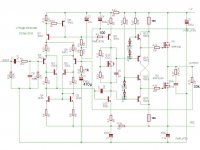
2) To avoid that the small signal transistors NCC551 (and/or 2N4501) can explode and burn (with an open flame) in case of internal short of a power-MOSFET, I can only recommend to LJM (if he reads this) to consider including two 10k resistors as indicated in the modified schematic attached below. It was tested in LTSPICE and has no negative impact on the amp's performance (output power, THD, intermodulation, all remains as before). In a power-MOSFET fail incident, these resistors would limit the current to a few milliamps, so that no danger could result from the totem pole transistors anymore.
Other Recommendations:
I found that the THD with the L7 is low up to 1 kHz, but can increase significantly up to 0.2% from 1kHz to 20 kHz, due to crossover distortions, depending on how well the MOSFET pair is matched. The bias is fix by the voltage divider resistor pair 9.1k/10k at the bias transistor gate. This is a "safe" configuration, but often not sufficient to cancel the crossover distortion at higher (i.e. 10kHz) frequency. Leaving it up to the hobbyist to adjust idle current himself, may be not a good advice, because within a few hundred ohms only, the idle current goes through the roof and the power-MOSFETs ....bang! I found a good compromise with both voltage divider resistors at the bias transistor exactly 10.0 kOhm. They must be measured and selected for being precisely the same, tolerance of 1% is not enough. Therefore, I am not sure if that is a practical solution for a DIY kit. Nevertheless, it provides improvement of THD and IM-distorions.
Further improvement is possible with a 33pF capacitor parallel to the resistor in the NFB-line. In early versions of the L7 the resistor was 10k and the corresponding foot-resistor in series with the NFB electrolytic cap (1000µF formerly) was 330 Ohm. In the newer L7 version the NFB resistor was increased to 33k, the NFB electrolytic cap changed to 470µ and the series resistor with the cap 1k. Thus, a 33pF foil cap parallel to the 33k resistor (formerly 10k) in the NFB improves higher frequency distortion. Why only 33pF? Higher capacities (47pF and up) can cause oscillation.
Perhaps some L7 users find this review useful.
Best Regards
Reinhard
This failure mode is a result of the IRFP9240/IRFP240 exceeding the operating junction temperature limit, 150°C, according to the data sheets or SOA limit, which is about 5A at 55V Drain_Source voltage with 10ms pulsed signal (100Hz). According to LJM, +/-55V rail supply is allowed for the L7 amp. With thermal resistance junction-case of 0.83 W/°K, the L7 amp's heat sink is very critical and sufficient heat dissipation very difficult to accomplish for 50W and more into 4 Ohms.
Conclusion:
The L7 amp is not "safe" to use for >50W into 8 Ohm load or >30W into 4 Ohm load because the MOSFET' thermal resistance junction-case is 0.83 W/°K. To maintain at 50W (sinus) a junction temperature of <150°C it requires a total thermal resistance (incl. heat sink) of 0.5 W/°K or better. That however, is not possible (or only possible for a short time) with a single power transistor pair, given the high MOSFET junction-case thermal resistance of 0.83 W/°K (data sheet). This is even so if the heat sink's thermal resistance is less than 0.5 W/°K.
Safety Precautions:
1) Because there is no resistor in the power amp stage in series with the source or drain, a very high current will flow in case a power MOSFET becomes internally shorted. Usually, the resistor would open in such case to prevent the worst. Not here however, because the L7 circuit comes without it. Therefore, it mandatory, that the rail supply voltage lines +Vcc and -Vee are protected by a fuse each (fast type), which opens when a specified current is exceeded, i.e. 1.5 amps). This is actually "good practice" and would not need to be highlighted, but can be forgotten sometimes.
2) To avoid that the small signal transistors NCC551 (and/or 2N4501) can explode and burn (with an open flame) in case of internal short of a power-MOSFET, I can only recommend to LJM (if he reads this) to consider including two 10k resistors as indicated in the modified schematic attached below. It was tested in LTSPICE and has no negative impact on the amp's performance (output power, THD, intermodulation, all remains as before). In a power-MOSFET fail incident, these resistors would limit the current to a few milliamps, so that no danger could result from the totem pole transistors anymore.
Other Recommendations:
I found that the THD with the L7 is low up to 1 kHz, but can increase significantly up to 0.2% from 1kHz to 20 kHz, due to crossover distortions, depending on how well the MOSFET pair is matched. The bias is fix by the voltage divider resistor pair 9.1k/10k at the bias transistor gate. This is a "safe" configuration, but often not sufficient to cancel the crossover distortion at higher (i.e. 10kHz) frequency. Leaving it up to the hobbyist to adjust idle current himself, may be not a good advice, because within a few hundred ohms only, the idle current goes through the roof and the power-MOSFETs ....bang! I found a good compromise with both voltage divider resistors at the bias transistor exactly 10.0 kOhm. They must be measured and selected for being precisely the same, tolerance of 1% is not enough. Therefore, I am not sure if that is a practical solution for a DIY kit. Nevertheless, it provides improvement of THD and IM-distorions.
Further improvement is possible with a 33pF capacitor parallel to the resistor in the NFB-line. In early versions of the L7 the resistor was 10k and the corresponding foot-resistor in series with the NFB electrolytic cap (1000µF formerly) was 330 Ohm. In the newer L7 version the NFB resistor was increased to 33k, the NFB electrolytic cap changed to 470µ and the series resistor with the cap 1k. Thus, a 33pF foil cap parallel to the 33k resistor (formerly 10k) in the NFB improves higher frequency distortion. Why only 33pF? Higher capacities (47pF and up) can cause oscillation.
Perhaps some L7 users find this review useful.
Best Regards
Reinhard
Attachments
Last edited:

Very few hifi amps can survive 50W into 4ohms for an extended period of time , let alone with a single output pair and 55v rails. Just saying.
I can only agree.
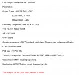
Pls. see in the attachment what'sclaimed by the seller.
That's why I checked.
Thereis at least another post in this forum describing fire/explosion. I tried to find it with the search function, but didn't manage yet.
Regards
Reinhard
Pls. see in the attachment what'sclaimed by the seller.
That's why I checked.
Thereis at least another post in this forum describing fire/explosion. I tried to find it with the search function, but didn't manage yet.
Regards
Reinhard
Attachments

Why is there zero bias Ljm.
If you can forgive my attempt at humor perhaps it is because far fewer amplifiers explode when they are shipped with zero bias and fixed bias. (And sometimes with significantly mismatched components.)
Otherwise with a fixed bias a certain part of the manufactured distribution will be biased too high with heat, stability and reliability issues.
The solution in many commercial amplifiers is a bias trimmer and a manual trim step in the production/test process.
The other end of the manufactured distribution will of course be biased too low.
Last edited:
I am running a single pair of the IRFp9140 and irf240 on 40v rails with no problem into 4 ohms. clipping is at 80w RMS into 8 ohms 152w into 4 as power supply sags.
The amp is a modified Litchstark from Valery Zaichenko's thread.
my speakers are easy loads > minimum 6 ohms average 9 ohms
The amp is a modified Litchstark from Valery Zaichenko's thread.
my speakers are easy loads > minimum 6 ohms average 9 ohms
I think whether or not someone has a problem with a particular amplifier depends on many factors.
One is the power supply they use, another is the difficulty of the load as just two examples.
But on top of that there are seemingly random factors. For example, with the same power supply and same load one of my MX50x2 burned up and the other was ok.
My strong suspicion is that the components and bias were unmatched contributing to a failure. (Based upon the evidence I found from probing, disassembling and rebuilding the surviving board of the pair and measuring all of the critical components out of circuit.)
Someone else with another MX50x2 also took out their output transistors and reported big mismatch. Then I took apart my L20.5 and found one board/amp nicely matched and the other with one transistor of concern out of the eight.
If I had received two MX50x2 with nicely matched components everything might have been fine. Also if I had not used 50V rails I might never have noticed.
For the future I have developed a few rules of thumb for my own builds:
1. Try to buy DIY (not assembled).
2. Measure and match all components.
3. Learn special matching requirements such as Baxandall diodes in MX50x2 lower output pair.
4. Buy outputs and perhaps drivers from authorized distributors and carefully match.
5. Add the missing Zobel networks, etc.
6. Buy and replace certain potentially problematic components. Maybe an example: Replace 2SC1815 transistors with a higher voltage device if warranted in a particular design. Sometimes the kits are "overly optimistic" on voltage and power specifications and sometimes they use components with voltage and power ratings that are a bit too low. [Sometimes it is a good idea to stay well away from the extremes of the claimed power and supply voltage specs.]
7. Replace certain 1/4W resistors with 1W or 2W.
8. Replace certain commonly faked capacitors. (High cost/high performance series.)
9. And the list goes on. Perhaps add a few current limiting resistors and some protection diodes. (Drivers and/or bias stage.)
Last edited:
Measurements on the L7 0.3 % distortion by 50 w output.
Are you sure? I thought it was THD <0.01% 100W 1kHz?
With Output Power 150W 8R DC + - 56V, 300W 4R DC + - 56V, 350W 2R DC + -45V?
It reminds me of when I was younger and I bought a car audio amplifier which was rated at something like 300W on the glossy box. I took it apart and it contained two little 5 pin TO-220 chip amps.
A friend of me who has worked with audio for 60 years measured it. And there almost zero bias. Wich resistors is the bias adjustment?
I have modified the L20.5 and MX50x2 to adjustable bias and that was easy.
For the L7 I suggest you find someone who has successfully modified it. With the reports of failures I am hesitant to just say "adjust the resistors on the MOSFET 'Vbe Multiplier'".
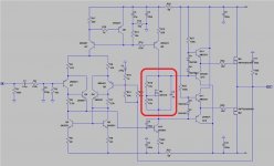
I have enclosed a schematic with the MOSFET 'Vbe Multiplier' marked. But I am not sure you should just replace the lower resistor with one size larger multi-turn (Bourns 3296W) trimmer. (Without first discussing with someone else who has done this on the L7 safely.)
When I replaced the lower bias resistors (on L20.5 and MX50x2) with a trimmer I used one size larger (2k to replace 1k, for example) and I started with the trimmer set to maximum (2k). Note that I soldered the wiper to one end of the trimmer resulting in a two terminal variable resistor. Others use a combination of a fixed resistor and a trimmer. I found one 3296W multiturn fit the PCB well and provided sufficient adjustment resolution.
I think I read somewhere that someone suggested a bipolar Vbe multiplier for better (thermal) stability but you need to discuss with someone with more experience. I have not gotten to my L7 yet. It is assembled but I am busy with the others especially after one of the MX50x2 boards incinerated. (The rebuilt one with very carefully matched components sounds very nice.)
I don't want to give you wrong advice so please search for someone who has figured the L7. When you do figure it out please post since I will need to adjust the bias on my L7 also.
There seems to be some discussion here: LJM Audio
For the L7 I suggest you find someone who has successfully modified it. With the reports of failures I am hesitant to just say "adjust the resistors on the MOSFET 'Vbe Multiplier'".
I have enclosed a schematic with the MOSFET 'Vbe Multiplier' marked. But I am not sure you should just replace the lower resistor with one size larger multi-turn (Bourns 3296W) trimmer. (Without first discussing with someone else who has done this on the L7 safely.)
When I replaced the lower bias resistors (on L20.5 and MX50x2) with a trimmer I used one size larger (2k to replace 1k, for example) and I started with the trimmer set to maximum (2k). Note that I soldered the wiper to one end of the trimmer resulting in a two terminal variable resistor. Others use a combination of a fixed resistor and a trimmer. I found one 3296W multiturn fit the PCB well and provided sufficient adjustment resolution.
I think I read somewhere that someone suggested a bipolar Vbe multiplier for better (thermal) stability but you need to discuss with someone with more experience. I have not gotten to my L7 yet. It is assembled but I am busy with the others especially after one of the MX50x2 boards incinerated. (The rebuilt one with very carefully matched components sounds very nice.)
I don't want to give you wrong advice so please search for someone who has figured the L7. When you do figure it out please post since I will need to adjust the bias on my L7 also.
There seems to be some discussion here: LJM Audio
Attachments
Last edited:
Hello, for curiosity, does anyone ever measured a wide (4 Hz to 350 kHz) frequency responce/bode plot of the L7 project? I was wondering of how great the frequency responce is (both magnetudes and phase shift).
I made adjustable bias on the L7. It is only running at abt 30V supply. I tried it with high Iq, and I liked it best around 0,2A if I remember correctly. Have not used it much, but I would say sound is 'soft', not so detailed but pleasant to listen to. Measures ok to, but rising distortion in the treble, this was improved with more bias.
- Home
- Amplifiers
- Solid State
- L7 MOSFET DIY amp kit by LJM