I have seen evidence in previous posts and dealings with China that they do indeed have different arithmetic from our "conventional" sums.
Hi Andrew They are not the only ones.
I do remember in my younger days ? Asking for an explanation at a Hifi show.
Why do you state that the 405 is your first genuine Quad amplifier ? Its stereo.
Well its like this sir,
It has stereo outputs and the current dumping circuitry uses another two output devices.?
Next door Max T was using a Beard amp.(He was also laughing)
Excuse me sir . When I have used this amp for a week or so.
Should it get and electric shave or a wet one?.
Also thanks to Maty for suggestion re L12 supplier.
Other posting re power supply should not really be posted on the thread.
I do have an excellent 55v dc + and _ 20k power supply already and never liked switched mode in any system.Period.
Dave[/QUOTE]
B: yes. I have a L150W type power amplifier.
It USES six IRFP250 only[/QUOTE]
I am just curious why the Input signals and output connector are so close together on this amp.. Otherwise I will think this will be my next kit/board
B: yes. I have a L150W type power amplifier.
It USES six IRFP250 only[/QUOTE]
I am just curious why the Input signals and output connector are so close together on this amp.. Otherwise I will think this will be my next kit/board
"never liked switched mod"
Audio Myth - "Switching Power Supplies are Noisy"
-> https://benchmarkmedia.com/blogs/ap...audio-myth-switching-power-supplies-are-noisy
Audio Myth - "Switching Power Supplies are Noisy"
-> https://benchmarkmedia.com/blogs/ap...audio-myth-switching-power-supplies-are-noisy
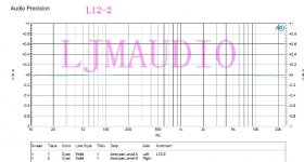
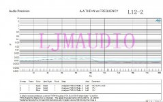
About the test.
I use a 200 va AC24-0 to 24 v transformer. black
Power strip with 4 * 5600 uf
Load of 8 ohm resistance of 1000 w.
Use a larger capacity of capacitance will decrease the distortion of low frequency.
But I don't have any more.
I use a 200 va AC24-0 to 24 v transformer. black
Power strip with 4 * 5600 uf
Load of 8 ohm resistance of 1000 w.
Use a larger capacity of capacitance will decrease the distortion of low frequency.
But I don't have any more.
Attachments

Hi,
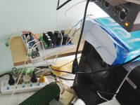
I've got two board of L12-2 from TZT Trading.
But I found the sound lacks of resolution when I compare the L12-2 with my HK3490 Class AB and with an Aiwa CX-Z720 (Best sounding). It lacks details in all the midrange, as the sound was not clear.
I've tested the boards with 3 different power supply:
- 2 x 35VDC Transformer with rectifier 10.000uF each rail
- 2 x 12VDC Battery
- 2 x Linear power supply +-14V with LT1083 regulators 10.000 uF per rail
There were not so many differences between them.
I tried to EQ with my AK4495 DAC but I think it's not a matter of EQ, it's about the separation of voice and instruments.
I've changed the input capacitor with a 1uF 50V film type but there is not much change.
I've also added 100nF 100V f¡lm capacitors to bypass all the electrolitic capacitors on the back of the board but again the major problem is not solved.
I've got the amp running pink noise with resistors for over 20 hours.
DC offset is around 8-10mV, output does not make any hum or hiss on the speakers.
Both boards has been tested together and separately with stereo and mono recordings.
What I can test or mod to improve the sound? Maybe some parts are fake?
Sound it's not bad at all, but it has some kind of blurryness that the other 2 amps dont show.
The board is this one:
Any help is greatly appreciated. Thanks!
I've got two board of L12-2 from TZT Trading.
But I found the sound lacks of resolution when I compare the L12-2 with my HK3490 Class AB and with an Aiwa CX-Z720 (Best sounding). It lacks details in all the midrange, as the sound was not clear.
I've tested the boards with 3 different power supply:
- 2 x 35VDC Transformer with rectifier 10.000uF each rail
- 2 x 12VDC Battery
- 2 x Linear power supply +-14V with LT1083 regulators 10.000 uF per rail
There were not so many differences between them.
I tried to EQ with my AK4495 DAC but I think it's not a matter of EQ, it's about the separation of voice and instruments.
I've changed the input capacitor with a 1uF 50V film type but there is not much change.
I've also added 100nF 100V f¡lm capacitors to bypass all the electrolitic capacitors on the back of the board but again the major problem is not solved.
I've got the amp running pink noise with resistors for over 20 hours.
DC offset is around 8-10mV, output does not make any hum or hiss on the speakers.
Both boards has been tested together and separately with stereo and mono recordings.
What I can test or mod to improve the sound? Maybe some parts are fake?
Sound it's not bad at all, but it has some kind of blurryness that the other 2 amps dont show.
The board is this one:
An externally hosted image should be here but it was not working when we last tested it.
Any help is greatly appreciated. Thanks!
In that case the L20 might be more likely...Hi everyone!
Since my Fischer BA-6000 blew up (see here), I'm thinking about replacing the power amp board and save all the other circuitry.
The transformer outputs 44V - 0 - 44V with no load and I don't know if the L12-2 board can handle +/-60V.
Any suggestion?
Thank you
Just Google "Buy L12-2 Ebay" and voila!
L12-2 Stereo Audio CLASS AB Power Post-Amplifier Board DIY kit dual 2.0 channel | eBay
Mono Class AB L12-2 Power Amplifier board Assembled 120W + - 55V | eBay
Note: Original kits came from other stores such as Along 1986090 and were available completed with heatsink attached. Current supplies from Sepstore, Doukmall etc are often kits of parts without heatsinks or may be complete. Some kits have been supplied with cheap output transistors instead of the LAPT Sankens shown. I have no association with these suggested suppliers so be careful where you buy and check what is actually offered.
Last edited:
Just Google "Buy L12-2 Ebay" and voila!
L12-2 Stereo Audio CLASS AB Power Post-Amplifier Board DIY kit dual 2.0 channel | eBay
Mono Class AB L12-2 Power Amplifier board Assembled 120W + - 55V | eBay
Note: Original kits came from other stores such as Along 1986090 and were available completed with heatsink attached. Current supplies from Sepstore, Doukmall etc are often kits of parts without heatsinks or may be complete. Some kits have been supplied with cheap output transistors instead of the LAPT Sankens shown. I have no association with these suggested suppliers so be careful where you buy and check what is actually offered.
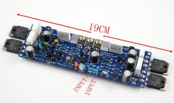
This is the original.
Other colors. Other elements, the transistor. Is not the real thing.
😀
Attachments
hi, I bought this kit, l12-2, finished assembling but as soon as I feed it with 55volt and at the exit it gives me a voltage of -54volt, I checked everything thoroughly but I do not find any problem, can someone help me?
Hello. Order L12-2 version 3, received version 4. Is it a beautiful fake or a new version? If the new version, what changes have been made?


Only I can say that the new LJM amps the logo changed to panda bear like your v4 board.
LJM L20.5 is the last amp. You can see the new logo:
![URL]](/community/proxy.php?image=http%3A%2F%2F%5BURL%5Dhttps%3A%2F%2Fwww.thanksbuyer.com%2Fimage%2Fcache%2Fdata%2F201807%2F58652%2F1532398522-3-750x750.jpg%5B%2FURL%5D&hash=cb1bfe7786e70e5684f7276b7a0f2dea)
LJM L20.5 is the last amp. You can see the new logo:
Hi everyone,
I've been reading calvin's page about the l12-2 and it state that
"The audio signal first passes a bandpass filter made up from R14/C7 and C5/R18" and was wondering if it would be possible to change the the low and hi cut of frequencies.
I search the web but didn't find any calculator that seems to match and make sens on this board shematics
any link is more that welcome, I'm not afraid of readings.
by exemple, I was wondering wich resistor and caps should I change, and to what value in order to get a cut of frequency of 250 or 300Hz instead of the logical 20Hz.
Thanks in advance. Best regards.
hi everyone and thanks for the link, even if I can't read it, it seems like regular passve high pass and low pass filter.
but applying the formula gives for the low pass filter made of the couple R14 (1KOhm)/C7 (68µf) gives a cut of frequency of Frequency: 2.3417010116 Hz
and the high pass filter made of the couple C5 (10µF or 33µF) and R18 (10KOhm) gives a cutoff frequency of :
Frequency: 1.5923566879 Hz
I guess I am greatly messing something up here...
- Home
- Amplifiers
- Solid State
- L12-2 CFP Output amp 120W*2 8R