Well, I did find and not surprising since the load is nothing like I had assumed, that the unloaded voltage was only about 0.2 volts above loaded.
I will disconnect from the HDPLEX module to measure to be safe.
Now to build one of these to power one of Mr. Rothacher's MOFO amplifiers.
I will disconnect from the HDPLEX module to measure to be safe.
Now to build one of these to power one of Mr. Rothacher's MOFO amplifiers.
Seriously, I feel like an idiot. The LM334 is overheating. I put a single 5.6V zener as Vref and an 18R current set resistor due to the lack of 12R value. What is going wrong? Could it be oscillating? I even disconnected the Vref circuit from the sziklai.
My bad, got it reversed.
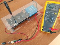
Just tested it. 5V unloaded, goes to 4.8V when loaded with 2A. 100mR output impedance?
Voltage across D11 is satisfactory - 7V
Edit: Doing it on a prototype board to test on my Pi
Just tested it. 5V unloaded, goes to 4.8V when loaded with 2A. 100mR output impedance?
Voltage across D11 is satisfactory - 7V
Edit: Doing it on a prototype board to test on my Pi
Last edited:
So it was just wrong connection. Built as standard with Leds and everything I measured 25mR at 2A. Including the board loss. Let it settle a bit thermally first. Maybe the Zener has a highish dynamic impedance at the particular bias current also. Or the driving BJT needs bit more base current sourcing available. Try with 10R LM334 setting resistor instead of 18R when not having the 12R for 5mA. Compare the 5V6 Zener vs three red Leds too. Less noisy at least.
My time of development notes as I saved them:
L-Adapt breadboard data
----------------------
1.73V main output per DC10EWA lit segment @ 5mA
Up to 1V extra from 200R trimmer
With 7.5V input 5V output:
0.035R voltage source impedance at 1A load
0.025R voltage source impedance at 2A load
0.020R voltage source impedance at 3A load
Over-voltage at zero load 90mV
Open plan drift 65C board sink +40mV 6mins
Open plan drift 65C board sink +30mV full time
LM334 0.064V ref & 12R setting resistor ~5mA
NJW0302G TO-3P PNP series pass element
F1 Slow blow 8A
Bridge diodes rating as above
---------------------------------
Are you using the exact BOM transistors and low resistance tracks?
P.S. Monitor the AC ripple at C4 when on high amperage testing. It can shoot to quite high pk-pk eating away most of the DCin-DCout no load margin. Its must be still allowing for 2.5V DC leftover across the pass BJT for good Zo.
Salas,
For my experiment, the transistors are not by the original BOM, they are MJL1302A and BD139
For my experiment, the transistors are not by the original BOM, they are MJL1302A and BD139
Your pass transistor means business but the driver transistor is chunkier in the original and that could be a thing.
Some pictures and use detail of my build here..
Show your audio system
Looking forward to my next 2 boards from the current GB...so many ways to improve stock supplies for audio devices.... next an android powering methinks...🙂
Show your audio system
Looking forward to my next 2 boards from the current GB...so many ways to improve stock supplies for audio devices.... next an android powering methinks...🙂

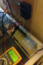
I'm about to supply the RPi but I can't figure out why my DMM shows 4VAC (9.8V unloaded, 8V 30VA transformer) at the L-Adapter input. It seems to work well with 18Ω@5V load (and more than 6V at D11).
User mistake? I'll check again 😵'
User mistake? I'll check again 😵'
Last edited:
L-Adapter, when all is well done, only pulls 5mA for its Vref plus what bleeds the R1 1k Vout preloading resistor. 5/1000=5mA bleed when set at 5V out and so on and so forth.
OK Salas & guys,
seems I can't handle my DMM properly sometimes... steady 9.75VAC at primary.
Voltage drift in my case is around 10/15mV when warm. 8VAC 30VA transformer and over 6VDC headroom, even when throttling at startup (Raspberry Pi 2B and Allo DigiOne).
It's working fine but that crappy Micro-USB socket I've used has a loose contact* and I hope that won't harm the SD Card. Can't tell about sound, too late now.
*Anyone for a quality Micro-USB socket to solder or a nice'n large gauge cable to sacrifice? Next move not planned but I need a reliable socket 😉
Attachments
- Home
- Amplifiers
- Power Supplies
- L-Adapter