You're welcome.
Only LEDs is less VRef impedance than LEDs + resistor vs the current source chip's impedance. The higher those impedances division the more the resulting PSRR. So far so good. Depending on the thermal coefficient of the LED type used and the number of employed units, check if there is any significant negative going Vout drift or not.
Only LEDs is less VRef impedance than LEDs + resistor vs the current source chip's impedance. The higher those impedances division the more the resulting PSRR. So far so good. Depending on the thermal coefficient of the LED type used and the number of employed units, check if there is any significant negative going Vout drift or not.
With 15 leds and 180R I get a steady 23.99 volts with the platter spinning.
No drift anywhere but then I have not approached all leds.
I considered adding another led but I ran out of room on my little board.
I think I can live with this. With pleasure.
THANKS for the help, counsel and being the extraordinary fellow you are.
No drift anywhere but then I have not approached all leds.
I considered adding another led but I ran out of room on my little board.
I think I can live with this. With pleasure.
THANKS for the help, counsel and being the extraordinary fellow you are.

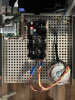
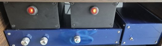
Is there a picture of your 24V L-Adapter you can post? Interesting because of the daughter board with the odd shaped low noise LEDs.
I have the L-adapter up and running now, everything is working to my satisfaction thank you 🙂
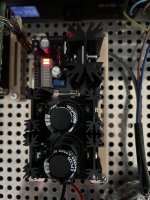
But the CRT heatsink seems to be running a bit hot. I have a hard time measuring it, but it's hot to touch, 5 sec touch is about all I can take. Same temp at idle as when playing DSD128 with Volumio on Raspberry pi 5. Playing via ssd on the pcie input.
My setup
L-adapter
50VA toroid, 2x9v in parallel
5.1v dc out
2 leds (seems to be ok at all time)
Is the heat ok or is there any measures I can take to see if anything is wrong?
From your description (5 sec longest touch) that sink could be at 60C or about.
This kind of heat isn't threatening the sink mounted main transistor short term. Though better not to enclose. Elevated box ambient temp will not promote best longevity of all parts. Especially electrolytics. 10C less would be beneficial.
Same temp at idle and when playing DSD rather points toward more than enough spare voltage across the reg due to healthy mains level & highish transformer output.
Measure two things at idle and at play: AC across L-Adapter's transformer input connector and DC across D11 diode. With this basic data we can talk possible measures. A picture also helps.
Hey,From your description (5 sec longest touch) that sink could be at 60C or about.
This kind of heat isn't threatening the sink mounted main transistor short term. Though better not to enclose. Elevated box ambient temp will not promote best longevity of all parts. Especially electrolytics. 10C less would be beneficial.
Same temp at idle and when playing DSD rather points toward more than enough spare voltage across the reg due to healthy mains level & highish transformer output.
Measure two things at idle and at play: AC across L-Adapter's transformer input connector and DC across D11 diode. With this basic data we can talk possible measures. A picture also helps.
I measured the AC input to 9.5 and across D11 to 5.75.
I’m gonna let it idle for a couple of hours, but I’m afraid it’s rising to above 70°C
I also took some pictures if it helps.
Attachments


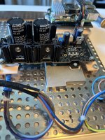
Looks very well put together. Congrats. Did it also differentiate the sound in your opinion?
Either a double the height same footprint board level sink, or direct mounting of the main transistor sideways to the perforated floor panel.
The second option would spare the nice (3D Printed?) base though. You are not interested in slow 120mm fan forced air cooling I presume.
Either a double the height same footprint board level sink, or direct mounting of the main transistor sideways to the perforated floor panel.
The second option would spare the nice (3D Printed?) base though. You are not interested in slow 120mm fan forced air cooling I presume.
Thanks! First impression gave it a fuller soundstage atleast. Haven't got around to a/b test it yet, but I will.
I wouldn't prefer either double height heatsink or a fan, coz I wish to keep the case rather slim. The second option is more interesting though, which means to put the transistor directly flat on the floor panel? The only problem is I need the 3d-printed base because it's perfectly fitted to the floor, the mounting holes of the L-adapter does not fit. Would it be ok to elongate the legs of the transistor to reach the floor? Or have an aluminum base fastened to the floor and have the transistor mounted on the extra base? Or do you have any other idea 🙂
I wouldn't prefer either double height heatsink or a fan, coz I wish to keep the case rather slim. The second option is more interesting though, which means to put the transistor directly flat on the floor panel? The only problem is I need the 3d-printed base because it's perfectly fitted to the floor, the mounting holes of the L-adapter does not fit. Would it be ok to elongate the legs of the transistor to reach the floor? Or have an aluminum base fastened to the floor and have the transistor mounted on the extra base? Or do you have any other idea 🙂
You are welcome. Nice. First of all keep in mind to use an isolation pad in the directly flat to the floor cooling scenario. Else the transistor will create a catastrophic short of positive rail to grounded chassis. You confirm no continuity between transistor tab and chassis with the DMM's continuity buzzer (no beep). Having an extra aluminum base fastened to the floor like a step is good because it has generous non perforated flat surface for the whole silicone pad. Will interface the thermal energy and spread it to the floor. Use thermal paste between metal mating surfaces.
What was the room's ambient temperature during that evaluation? Rpi 5 was running DSD? By the way, those voltages are in acceptable range. If D11 had 4V as an example because of an 8VAC Tx the board level sink would be cooler but we got to also allow Vin-Vout margin for lowered mains during heavy consumption hours, and/or heavier Rpi current draw situations due to powering USB peripherals or running heavier programs etc.Hey,
I measured the AC input to 9.5 and across D11 to 5.75.
I’m gonna let it idle for a couple of hours, but I’m afraid it’s rising to above 70°C
I also took some pictures if it helps.
I made some measurement in my drawing of the enclosure, and if I get rid of the spacers between the floor and 3d-base I can fit the largest of the heat sinks. This is 63.5 cm and the current one is 38.1. I hope this will be sufficient to reduce the overall ambient temp when enclosed.
Try it. It will bring it down enough but nothing like chassis floor sinking through an aluminum interface block.
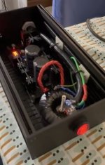
Wasn’t easy to desolder the heatsink and transistor… almost gave up 🙂 But finally made and mounted it on top of an aluminum block on the floor instead. So this is the setup for now. Tested for continuity and no beep so I take it’s allright.Try it. It will bring it down enough but nothing like chassis floor sinking through an aluminum interface block.
Attachments
It looks well put together. It should spread heat nicely. No beep between the transistor's metal tab and the chassis means success i.e. the insulator in-between is the right size and not torn. The sink legs especially are difficult to pull out after being soldered. Did you use solder wick?
I used both solder wick and suction, but there was some part always left. In the end I had to use some brute force 😳Did you use solder wick?
It worked and I’m satisfied now and can continue with the parts for the enclosure. Also gonna need a power switch connected to the Rpi and a display.
Attachments
Last edited:
Nice to know. You are welcome. Did you go directly from their SMPS bricks to L-Adapters or you had also tried other linear PSUs before for the Pi and the router?
No, I haven't tried another linear PSU. I have in my lab a couple of Keithley that I was temping to try, but I didn't. As @katopis advised me, I went directly to L-adapters. Firstly, I checked the sound using only one, connecting it to the router. The sound was clearer and analytic; you can directly notice it, but when I connected the second l-adapter to the Pi , it was another world. The frequency range, the dynamics, the stage, and the analysis were AMAZING. I can appreciate now, even more, my preamp, especially at low frequencies. I put everything together yesterday, so I guess that it would get better over time. But the zero distortion and the analysis are unbelievable. Imagine I was thinking of getting another L-adapter for my preamp, but @katopis told me I should not touch it and leave it as it is 😛 .
- Home
- Amplifiers
- Power Supplies
- L-Adapter