DRONE7 I admit I am impressed. Congratulations!
Thank you ...though all credit goes to you (and T-Bag!) for your superbly detailed instructions, support, and design !!
I am a rank amateur and understand very little of the theory... but know enough practical to muddle along and your answers to my questions have helped me to complete this project.
I am thrilled with the performance of both L-Adapters.
Are there positive clues in the quality of transcripts via this server when going from SMPS to linear power?
Are there positive clues in the quality of transcripts via this server when going from SMPS to linear power?
I have no test equipment to quantify.... only a lifetime involvement in the audio industry and a pair of ears that have served me well.
Totally subjective then... I find the transcriptions when powered by the L-Adapter and subsequently played via a digital media server to be more aligned with what I hear...and enjoy !.. from my analogue system....(Well Tempered Classic and Arm.. Plinius and Perreaux amplification and Shahinian Loudspeakers.)
This to me is very positive ! (others may not agree...🙂 ...)
Including cable drop to load?
No, i measured directly on l adapter terminal block not on load.
At 1.5A load it has about 0.03Ω output impedance. Not a simulation, those conclusions are from my board including the connector. So when multiplying numbers something like 50mV loading drop* is expected in your case. Unless the Vin-Vout margin is not good.
*But don't include any warm up shift, let it settle first.
*But don't include any warm up shift, let it settle first.
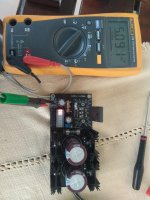
I have used 9v dc in as first test.
3 leds light(jumper set to 3) and trim for 5.090 Vout no load.
Then a 12R connected direct to L Adapter OUT.
I see 5.034 V out.
5.090/12=0.4A
0.4A*0.03R=0.012A
Is it something wrong?
PS now i see 0.03R is the out impedance at 1.5A😕
3 leds light(jumper set to 3) and trim for 5.090 Vout no load.
Then a 12R connected direct to L Adapter OUT.
I see 5.034 V out.
5.090/12=0.4A
0.4A*0.03R=0.012A
Is it something wrong?
PS now i see 0.03R is the out impedance at 1.5A😕
Attachments
Last edited:
0.057V drop divided by 0.4A gives 0.1425Ω
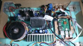
I kept no lower loading data than for 1A and it was giving 0.035Ω there. Those big parts need a substantial current pull to wake up well. My output transistor was ON Semi NJW0302G mounted on a board level sink during the loading drop test. Sink the TOSHIBA 2SA1943 too not to burn it by some mistake.
I kept no lower loading data than for 1A and it was giving 0.035Ω there. Those big parts need a substantial current pull to wake up well. My output transistor was ON Semi NJW0302G mounted on a board level sink during the loading drop test. Sink the TOSHIBA 2SA1943 too not to burn it by some mistake.
Thanks Salas,2SA1943 is without any heatshink and not well soldered yet because this will be mount on the bottom of the box when ready.0.057V drop divided by 0.4A gives 0.1425Ω
I kept no lower loading data than for 1A and it was giving 0.035Ω there. Those big parts need a substantial current pull to wake up well. My output transistor was ON Semi NJW0302G mounted on a board level sink during the loading drop test. Sink the TOSHIBA 2SA1943 too not to burn it by some mistake.
I will try to test at 1A or so latter.
Thanks Salas,2SA1943 is without any heatshink and not well soldered yet because this will be mount on the bottom of the box when ready.
I will try to test at 1A or so latter.
Mount on some plate or something for now. So you can test in higher current range with more realistic temperature both for good data and safety. I had tried with 2SA1943 too. Maybe it was little different for Zout than the ON Semi but not much. I don't remember the spot check numbers, but I remember comparable.
P.S.
I had put my Zo notes in the guide too "35,25,20mΩ Zo at 1,2,3A load & 2.5V Q2 Vce"
My DC load was electronic. Had a MOSFET and a control circuit with a pot. I was even revving it up from nothing to 3A and back fast but L-A did not show output overshoot.
I had put my Zo notes in the guide too "35,25,20mΩ Zo at 1,2,3A load & 2.5V Q2 Vce"
My DC load was electronic. Had a MOSFET and a control circuit with a pot. I was even revving it up from nothing to 3A and back fast but L-A did not show output overshoot.
Ok i can test using NJW0302G too,just for sure that we test under the same conditions.😉P.S.
I had put my Zo notes in the guide too "35,25,20mΩ Zo at 1,2,3A load & 2.5V Q2 Vce"
My DC load was electronic. Had a MOSFET and a control circuit with a pot. I was even revving it up from nothing to 3A and back fast but L-A did not show output overshoot.
I haven't electronic load but ...may be it's time for such a tool.
Last edited:
Yes i will test using a proper transformer and short cables.🙂Check the power source feed to L-A it won't sag too.
Now i use a wallpack D.C power supply and 1 meter long cable between this and L Adaptor.
Last edited:
I haven't electronic load but ...may be it's time for such a tool.
It doesn't need to be an automated heavy duty lab box when for once in a while few Watt use. Bench E-Loads can cost from hundreds to thousands. There are simple gadget board ones too.
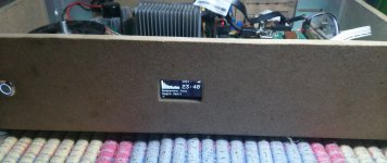
Liking the result? Does it really need such a big sink for RPi2?
Just tested without DAC. My Dac nit finished.
Not really, from test, it should be enough for 1A constan load.
It hard to cut the heatsink with handsaw 😀
- Home
- Amplifiers
- Power Supplies
- L-Adapter