AC line grounds are part of what forms some of the overall reproduction system ground loops. That's true even if system devices are plugged into the same outlet.
Which renders AP loopback tests of interconnects essentially meaningless. And why some of the most cutting edge and measurement focused manufacturers opted for high impedance instrumentation inputs.Tests of a single IC in solitary has very little meaning.
Example of an AP loopback test of a 'throwaway' RCA cable : https://www.audiosciencereview.com/...ton-rca-cable-review-ultra-cheap-cable.33473/

Some cable measurements I hadn't seen before described in a non-audio paper. Please see attached. Kind of looks like AC conductance is measured in way wherein DA displacement current is modeled to better understand complex capacitance.
Attachments
Last edited:
When all you have is an AP everything looks like an amp. One unified power supply, one very short and very low impedance internal ground plane return bypassing the interconnect, physically adjacent I/O; accurately replicating the way interconnects are never used. For contrast see ASR's 'energetic' forum discussion on low impedance power cords in the context of the GR Research power cord review, or PMA's investigation of the benefit USB isolators for audio measurements.
Can you expand on that, please? I went over and looked at the tests and they are identical cable in and cable out of the loop. But you are saying that the AP is far from real world use in an audio system. What do you see as the differences and problems?When all you have is an AP everything looks like an amp.
Let me put a graphic together....Can you expand on that, please?
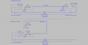
Here you go, quick LTScribble. It represents a still common scenario of unbalanced interconnecting of two audio devices with three wire power cords. Every such commercial device I own - Benchmark DAC, Sony power amps, etc. - hard tie the audio reference ground to chassis/AC third pin. In these cases it's reasonable the power cord is at minimum one of the audio current return paths to source. Depending on relative lengths and gauges of the power cord and interconnect it may be the primary path. Both are 'open to the air'.
In the AP loopback case the minimum ground impedance between I/O will be the AP's shielded and internal ground plane. No two boxes with potentially different ground potentials in this case. The interconnect's ground path potential carries nearly no current, depending again interconnect gauge. Holding the differences are of no consequence may be valid, holding they're equal is a stretch.
In the AP loopback case the minimum ground impedance between I/O will be the AP's shielded and internal ground plane. No two boxes with potentially different ground potentials in this case. The interconnect's ground path potential carries nearly no current, depending again interconnect gauge. Holding the differences are of no consequence may be valid, holding they're equal is a stretch.
Attachments
Thanks for the illustration, I missed it on Monday. I figured this might be what you meant, good to see it drawn out.
What would make a better test for interconnects? What would be a test representative of grounding problems in a typical system?
What would make a better test for interconnects? What would be a test representative of grounding problems in a typical system?
You might be able to use a clip-on pulse transformer to do something like introduce noise bursts into the ground loop. Then maybe look for evidence of audio signal noise floor changes and or distortion in response.
Other than things like that one could try breaking the loop and looking for reduced noise floor and or reduced distortion.
Other than things like that one could try breaking the loop and looking for reduced noise floor and or reduced distortion.
- Home
- Member Areas
- The Lounge
- Kunchur with more scientific audio cable