Hey guys,
I need your help. I built a prototype power amplifier in the lab using KT88 tubes in push pull ultra-linear. I am having a hard time biasing the tubes since the the cathode current keeps drifting up or down. I have the HT voltage set to a regulated 500V so I am biasing at 50ma quiescent current. Sometimes I can get the bias currents matched but when I play some music and then check the bias currents again, they are different by more the 20ma sometimes.
The tubes are Electro Harmonix KT88's and they are new (and supposedly matched), so I am wondering if this the reason. However, sometimes the bias can drift from 50mA to 80mA which is getting very close to the anode's maximum power rating. I am using an AnTek 70W toroidal output transformer wired for ultra-linear (I will eventually upgrade these to Edcor). What I find puzzling is that when the cathode currents are balanced, one tube's grid is at -57V (which is expected from the data sheet) and the other is around -48V. The bias supply is stable and regulated. Since these tubes are "matched" they should not be that different. If they are not matched, would there still be that big of a difference? Could I have a bad tube?
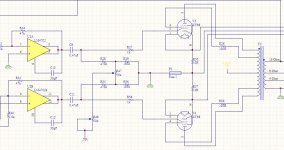
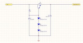
I was powering the tube filaments using a switching DC power supply at 6.3V. The bias regulator schematic is attached as well as my amplifier schematic. The power amplifier design is by Bill Christie which I found in an AudioXpress magazine (Jan 08 issue) titled A Hybrid High Fidelity Amplifier. The design uses the LM4702 driver chip to provide enough voltage swing to drive the grids. I was not using any global feedback.
Any ideas what could be the reason? The amp sounds quite good but when the bias currents get too far off there is some crossover distortion which is expected.
Thanks
I need your help. I built a prototype power amplifier in the lab using KT88 tubes in push pull ultra-linear. I am having a hard time biasing the tubes since the the cathode current keeps drifting up or down. I have the HT voltage set to a regulated 500V so I am biasing at 50ma quiescent current. Sometimes I can get the bias currents matched but when I play some music and then check the bias currents again, they are different by more the 20ma sometimes.
The tubes are Electro Harmonix KT88's and they are new (and supposedly matched), so I am wondering if this the reason. However, sometimes the bias can drift from 50mA to 80mA which is getting very close to the anode's maximum power rating. I am using an AnTek 70W toroidal output transformer wired for ultra-linear (I will eventually upgrade these to Edcor). What I find puzzling is that when the cathode currents are balanced, one tube's grid is at -57V (which is expected from the data sheet) and the other is around -48V. The bias supply is stable and regulated. Since these tubes are "matched" they should not be that different. If they are not matched, would there still be that big of a difference? Could I have a bad tube?
I was powering the tube filaments using a switching DC power supply at 6.3V. The bias regulator schematic is attached as well as my amplifier schematic. The power amplifier design is by Bill Christie which I found in an AudioXpress magazine (Jan 08 issue) titled A Hybrid High Fidelity Amplifier. The design uses the LM4702 driver chip to provide enough voltage swing to drive the grids. I was not using any global feedback.
Any ideas what could be the reason? The amp sounds quite good but when the bias currents get too far off there is some crossover distortion which is expected.
Thanks
Attachments
Though I'm not familiar with the front end at first glance the resistors (R28, R29, R35, & R36) in the bias circuit look too large Ohms-wise. 100K or so for R28 and R35 is more the norm. Not sure if this will help but it's worth a try.
Craig
Craig
I would try a different bias trimpot for each tube, your balance circuit might be the problem.
Jam
Jam
Though I'm not familiar with the front end at first glance the resistors (R28, R29, R35, & R36) in the bias circuit look too large Ohms-wise.
Absolutely. You need to have a path to ground from the grids. These tubes have large control grids which will accumulate unwanted electrons. They need a drain or the the tube will run away. GEC data sheets specify a maximum of 220k ohms for fixed bias applications where total dissipation is less than 35 watts.
I'm a rank amateur so my two cents may not even be worth that. But I'm with JAM. Why would anyone want to use a single bias pot even with so called "matched" tubes? Also, Why would you want to use separate regulators in the same circuit? Is this a current limitation thing for the transistors? If the DC voltage varies even a little bit wouldn't that throw the bias off? And if so would you need a DC balance pot? Also, how much does your mains voltage vary? And if you have a single bias pot shouldn't you have a single cathode resistor? As always I have more questions than anything else. Hope I haven't embarrassed myself.
Why would anyone want to use a single bias pot even with so called "matched" tubes?
There are two bias pots here. R48 sets the overall bias voltage, and R47 balances it between V3 and V4. It's a very usable arrangement.
And if you have a single bias pot shouldn't you have a single cathode resistor?
R30 and R37 aren't really cathode resistors in the traditional autobias sense. Their value is much too small to be useful as bias setting cathode resistors. They are only here as current sense resistors.
the resistors (R28, R29, R35, & R36) in the bias circuit look too large Ohms-wise.
That is the real problem. The KT88 demands a low resistance from the grid to the bias supply and the bias supply itself should be a low resistance. The data sheet shows a maximum total resistance for the entire bias path of 100K ohms in fixed bias operation. Your circuit has well over 500K. This can lead to bias drift and tube runaway, especially with new production tubes.
The bias circuit itself uses two pots one sets the bias level and the other sets the balance between the two tubes. This is a perfectly good circuit and is similar to other circuits I have used. The resistor values need to be scaled so that the total resistance is under 100K from each grid to ground.
GEC data sheets specify a maximum of 220k ohms for fixed bias applications where total dissipation is less than 35 watts.
I have a copy of a Genalex data sheet. It shows 220K for cathode bias and 100K for fixed bias. I use 130K in cathode bias since I have seen Chinese tubes go nuclear with 220K. Either way 470K is asking for a visit from the smoke monster!
Thanks for the advice everybody. After reviewing the GEC datasheet I see that a maximum of 100k from grid to ground is needed. I will change the resistor values and give it another try.
It's often worth putting some failure protection in to the pot R47 if the wiper goes open-circuit - perhaps by connecting the pot ends to the wiper by 470k or something similar. And also adding capacitive decoupling at the closest convenient point - ie. the wiper, or either arm of the wiper.
Ok, I changed r29 and r36 to 100k and removed r28 and r35. Although a big improvement, there is still some drift in current. Should I reduce r29 and r36 even further? I thought my caps could be leaky so I removed c8 and c11 and the bias was still drifting. I might have to try a completely new bias circuit🙁
Sounds like you've loaded the grid-grid impedance down hugely (<50k)??
Have you put a sensitive voltmeter on your bias voltage source and checked for variation over time - I think your bias regulator is drifting, and hence the idle current.
Have you put a sensitive voltmeter on your bias voltage source and checked for variation over time - I think your bias regulator is drifting, and hence the idle current.
The neg bias circuit you show suffers from some drift but not the amount you describe. Amongst the bias resistor values being too high, You don't mention what type those
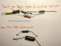
10R cathode resistors are. I had similiar quiescent runaway and discovered it was due to the 1W film o/p stage cathode resistors going high. I changed to wirewound 3W Dale types and problem solved. Any other ww types will suffice.
MAny modern oxide/film resistors cannot take transient impulses typically found in ouput stages and will go resistively soggy despite all power ratings being in order.
DO a test. Disconnect one from circuit, fix ohmmeter to it and apply the soldering iron and observe.
please reply
richy
Attachments
Hey guys,
I need your help. I built a prototype power amplifier in the lab using KT88 tubes in push pull ultra-linear. I am having a hard time biasing the tubes since the the cathode current keeps drifting up or down. I have the HT voltage set to a regulated 500V so I am biasing at 50ma quiescent current. Sometimes I can get the bias currents matched but when I play some music and then check the bias currents again, they are different by more the 20ma sometimes.
The tubes are Electro Harmonix KT88's and they are new (and supposedly matched), so I am wondering if this the reason. However, sometimes the bias can drift from 50mA to 80mA which is getting very close to the anode's maximum power rating. I am using an AnTek 70W toroidal output transformer wired for ultra-linear (I will eventually upgrade these to Edcor). What I find puzzling is that when the cathode currents are balanced, one tube's grid is at -57V (which is expected from the data sheet) and the other is around -48V. The bias supply is stable and regulated. Since these tubes are "matched" they should not be that different. If they are not matched, would there still be that big of a difference? Could I have a bad tube?
I was powering the tube filaments using a switching DC power supply at 6.3V. The bias regulator schematic is attached as well as my amplifier schematic. The power amplifier design is by Bill Christie which I found in an AudioXpress magazine (Jan 08 issue) titled A Hybrid High Fidelity Amplifier. The design uses the LM4702 driver chip to provide enough voltage swing to drive the grids. I was not using any global feedback.
Any ideas what could be the reason? The amp sounds quite good but when the bias currents get too far off there is some crossover distortion which is expected.
Thanks
There is a known issue concerning certain batches of Electro-Harmonix KT88s having unstable bias and not being able to balance even matched pairs. They drift as the temperature changes. I won't speculate why, just to say that on a forum dedicated to a PP KT88 amp using a CCS on the cathodes it is recommended to stay away from the EH KT88 because it was the only tube out of every brand tried that would not stay balanced. Certainly the circuit can exacerbate the problem but if you change brands of tubes you might find your bias problems disappear.
I have EH KT88s in my amp with no issues. I didn't get my quad from a bad batch.
I am using 10 Ohm 5W wire wound resistors for the cathode current sensing. I might try changing these resistors to another type just to see if it helps and also do the soldering iron test you recommended.The neg bias circuit you show suffers from some drift but not the amount you describe. Amongst the bias resistor values being too high, You don't mention what type those
10R cathode resistors are. I had similiar quiescent runaway and discovered it was due to the 1W film o/p stage cathode resistors going high. I changed to wirewound 3W Dale types and problem solved. Any other ww types will suffice.
MAny modern oxide/film resistors cannot take transient impulses typically found in ouput stages and will go resistively soggy despite all power ratings being in order.
DO a test. Disconnect one from circuit, fix ohmmeter to it and apply the soldering iron and observe.
I am going to reduced my grid to ground impedance further and check my power supply stability. If there are still drifting issues I might try a pair of 6L6's I have and see how they perform. If they are stable its probably a bad batch of EH KT88's.
What should the impedance be between grids?Sounds like you've loaded the grid-grid impedance down hugely (<50k)??
Just my 2 cents....while doing some breadboarding last week, I noticed drifty bias, turns out I had a defective bias potentiometer. Guess being new doesn't guarantee that it'll work properly.
Ray
Ray
Thanks TY for pointing out there are two bias pots. I'm currently finishing a pair of Mark II clones and using Joe Curcio's front end. But I used two separate bias pots rather than this arrangement. What is the advantage, if any, of one overall pot and a balance pot between them? Seems like separate circuits is a better idea?
Last edited:
In my breadboarding I used a 50k pot across a 150v regulated supply. I needed ~40v but the 150v regulated supply was the only one I had available.
With respect to grid-grid impedance, the real issue is the effective loading on the driver stage - if the driver was a valve(s) then increasing its loading has a significant influence on output signal swing. You may need to check the design, or test if changing the output loading of the driver has an impact.
Ciao, Tim
Ciao, Tim
- Status
- Not open for further replies.
- Home
- Amplifiers
- Tubes / Valves
- KT88 bias current keeps drifting