I'm glad I found this old thread.
It seems like Åke found better things to play with because I stumbled across his populated board on the Swedish version of Craigs list (blocket) and couldn't resist buying it.
I soon after found a pair of opts from a Chinese amp someone had dropped and after that bought a choke and PT.
The PT has the same windings as stated in the original schematic but without center taps.
I later bought some KT77 for the amp, I already had an ecc83 and 2x e80cc. Now a few years later I got some time over to tinker with it.
First now I noted that the opts doesn't have UL taps so I used triode mode instead since to my limited knowledge KT77 should be a drop in replacement for EL34. The second thing is that these "EL34" opts have 3k2 primaries.
Upon first test a 470uF cap blew up on me and now after replacing both the 470uf (before and after the choke) I got a B+ voltage of 530vdc and almost the same on G2.
Reading some more I get the feeling that KT77 might nog be such a good idea to use in this circuit and in triode mode.
I get mixed info depending on which datasheet I look at.
My tubes are newer JJ KT77s
I didn't know that the components on the PCB had meen altered from the original schematic.
My first thought was just to get some EL34 and put them in instead but I think I might run into some problems.
I am a novice I must admit.
You who have discussed this amp back in 2017, do you have any good advice here?
Last edited:
KT77 may not be used everywhere EL34 can be used. Consult manuals for hard data.
One thing that often makes trouble is that maximum value grid resistor is much smaller for
KT77 then EL34.
One thing that often makes trouble is that maximum value grid resistor is much smaller for
KT77 then EL34.
I know that now, I guess I read the wrong threads.
I have 1k going into grid1 and 100R between grid2 and plate.
I have 1k going into grid1 and 100R between grid2 and plate.
kmj,
petertub was not talking about the grid stopper resistor (for g1).
A 1k resistor is good for grid stopper use.
But instead, he was talking about the g1 resistor to ground.
Look at a GEC KT77 data sheet.
Maximum Rg (for g1) for cathode self bias operation is 500k Ohms.
Maximum Rg (for g1) for fixed adjustable bias operation is 250k Ohms.
The purpose of the g1 return resistor is to get rid of g1 grid current that the tube creates internally.
I am not talking about g1 grid current that is caused by overdrive voltage from the driver tube output to the KT77.
Too high of a resistance, and the tube goes into thermal run-away, and destroys the tube and/or the circuit that surrounds it.
Are your B+ filter caps rated for at least 600V or 630V (the B+ will be more than 530V until the KT77 pr the EL34 warms up and draws current)?
What is the current that the KT77 draws when the tube is warmed up, and the B+ is 530V?
The maximum plate dissipation of the KT77 is 25 Watts.
25 Watts / 530V = 47mA.
Can you please post a schematic of your amplifier and power supply, and give the voltage values too?
That will help us help you.
Troubleshooting by remote distance without an accurate schematic, is like a blindfolded Archer trying to hit the target with his Arrow.
Last edited:
Aha!
According the the schematic there is supposed to be a 100k resistor there but there are also some jumpers in that area for auto/fixed bias that didn't come with any explanation.
I jumpered the pins so that I got the negative voltage from the bias supply to pin5.
I'll check on the PCB after work.
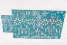
Looking at the photo of the PCB (the red ring) there are four solder pads and using V1 as an example the are, from top to bottom, V1-F-?-A. V1 and F are shorted on the board itself and I have the wire from the bias board connected to V1. To connect that pad to pin 5 on the tube I placed a jumper between the two pads below that one (F and ?).
The pins labeled A in the blue circle are left open as that goes to the cathode and that is already connected to ground via a 1R resistor.
Looking at the schematic next there is a block labeled 1-2-3 3-2-1 which seem to be the same as what I have described above.
The caps are rated to 450V (the schematic stated so) but now when I look at some photos of the PCB I notice that is states 500V.
The schematic I have is the one I have posted in this post but I have noticed that the cathode resistor have been altered to 1R instead of 10R.
I have to check each component to verify that nothing else have been altered.
Since the B+ voltage was so high I haven't dared to run it long enough to take any other measurements yet.
According the the schematic there is supposed to be a 100k resistor there but there are also some jumpers in that area for auto/fixed bias that didn't come with any explanation.
I jumpered the pins so that I got the negative voltage from the bias supply to pin5.
I'll check on the PCB after work.
Looking at the photo of the PCB (the red ring) there are four solder pads and using V1 as an example the are, from top to bottom, V1-F-?-A. V1 and F are shorted on the board itself and I have the wire from the bias board connected to V1. To connect that pad to pin 5 on the tube I placed a jumper between the two pads below that one (F and ?).
The pins labeled A in the blue circle are left open as that goes to the cathode and that is already connected to ground via a 1R resistor.
Looking at the schematic next there is a block labeled 1-2-3 3-2-1 which seem to be the same as what I have described above.
The caps are rated to 450V (the schematic stated so) but now when I look at some photos of the PCB I notice that is states 500V.
The schematic I have is the one I have posted in this post but I have noticed that the cathode resistor have been altered to 1R instead of 10R.
I have to check each component to verify that nothing else have been altered.
Since the B+ voltage was so high I haven't dared to run it long enough to take any other measurements yet.
Attachments
47mA through a 1 Ohm cathode resistor causes 47mV across the resistor.
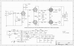
When an amplifier is turned on, until the output tube filaments and cathodes warm up, the B+ can be very high. That is due to the unloaded capacitor input power supply, like in the schematic.
'Working backwards', an unloaded cap input B+ that is 530V, has a power transformer secondary that is nearly 375VAC to the bridge rectifier.
What is your power transformer secondary voltage rating?
And, if everything else is OK, if the fixed adjustable bias pots are adjusted to be way to negative, the warmed up output tubes will not draw enough current, and the B+ will increase; similar to the B+ right after amplifier power-up.
The schematic is too blurry for me to read the component values, such as the resistors, etc.
Last edited:
My transformer has:
*335V secondary with 300mA
*70V and 100mA for bias
*6,3V 3,5A (2xKT77)
*6,3V 3,5A (2xKT77)
*6,3A 3,5A (ECC83+E80CC+E80CC)
None of the secondaries are centertapped.
*335V secondary with 300mA
*70V and 100mA for bias
*6,3V 3,5A (2xKT77)
*6,3V 3,5A (2xKT77)
*6,3A 3,5A (ECC83+E80CC+E80CC)
None of the secondaries are centertapped.
335VAC to a solid stage bridge rectifier, and then to a capacitor input filter will have almost 474VDC.
But, your 335VAC is the rating when you have 300mA load on it.
With a lower load on the windings, there is less voltage drop in the secondary windings, so you get a higher B+.
Also, if for example, you use 240VAC power mains on a 220VAC power transformer primary, you will get 240/220 = 1.09 times more voltage on the secondary.
335VAC secondary at 300mA, becomes 365VAC at 300mA (516VDC), for example.
With 1 Ohm cathode resistors, 47mV is 47mA. 4 x 47mA = 188mA
Perhaps the fixed adjustable bias pots cause the cathodes to only draw 30mA each, that would only be 120mA, causing the B+ to be quite high.
Lots to check here.
Are we getting closer?
Last edited:
A bridge rectifier that drives a 470uF capacitor is going to cause the power transformer secondary to get very hot.
Some of the schematics show either 47uF or 100uF from the bridge rectifier.
Some of the schematics show either 47uF or 100uF from the bridge rectifier.
We should have 230V from the socket and the primary are 2x115V so it should be correct.
The bias pots are adjusted to give close to -90V on pin5 so there shouldn't be any larger flow of electrons in those tubes yet.
I have bridge-470uF-Choke-470uF on B+.
I checked the supplied schematic and bought what it stated (470uF 450V).
The silkscreen on the PCB states 100-470uF 500V however.
Perhaps I should replace them with some smaller if it taxes the secondary winding?
Would replacing the choke with a power resistor help?
I am at work for some hours yet so I can't check
I installed a switch on the high voltage and with it turned off I turned the bias up to -48v on each tube, that should give me a bias current of 48mA with the 1R cathode resistor.
I left it on for a few minutes and then switched the high voltage on.
B+ measures 506VDC and I get 365VDC on the plates of the E80CC (ecc82 In the schematic).
Measuring over the 1R cathode resistors I get around 9mV.
I left it on for a few minutes and then switched the high voltage on.
B+ measures 506VDC and I get 365VDC on the plates of the E80CC (ecc82 In the schematic).
Measuring over the 1R cathode resistors I get around 9mV.
It seems like Åke found better things to play with because I stumbled across his populated board on the Swedish version of Craigs list (blocket) and couldn't resist buying it.
I decided to build it without a pcb, ,per to per instead.
I decided to build it without a pcb, ,per to per instead.
Did you end up changing anything on the board other than the cathode resistors?
Because there is something strange going on with this amp.
I am not accusing, just trying to eliminate possible sources.
Because there is something strange going on with this amp.
I am not accusing, just trying to eliminate possible sources.
Don't mind the voltage on the grids. Adjust the bias to get 48mA ( 48mV ) acrossI installed a switch on the high voltage and with it turned off I turned the bias up to -48v on each tube, that should give me a bias current of 48mA with the 1R cathode resistor.
I left it on for a few minutes and then switched the high voltage on.
B+ measures 506VDC and I get 365VDC on the plates of the E80CC (ecc82 In the schematic).
Measuring over the 1R cathode resistors I get around 9mV.
each 1R resistor. Tubes are different ( unless matched by me) and needs
different voltage to get a specific current.
Turning B+ off and on is a bad idea. Dont !
That did it!
-38v gave 48mA.
It works and buzzes like an angry beehive but it sits on a fibre board so that is perhaps to be expected.
Hopefully a metal chassi and shorter wires will fix that.
I have 452v om B+
110v on the ecc83 and 310 on e80cc.
But the volume doesn't go as low as it should. Minimum volume is still quite high.
Did you end up changing anything on the board other than the cathode resistors?
Because there is something strange going on with this amp.
I am not accusing, just trying to eliminate possible sources.
No I didnt change anything.
- Home
- Amplifiers
- Tubes / Valves
- KT77 P-P on a pcb from ebay...