Ryssen,
Looking at the circuit in your post, I see two things worth mentioning and I hope someone can correct me if I misunderstood.
1) it is not necessary to raise the el34 heaters at all.
2) the 12au7 heaters should be raised so as to keep the heater-to-cathode potential within limit (max. 90Vdc).
Looking at the circuit in your post, I see two things worth mentioning and I hope someone can correct me if I misunderstood.
1) it is not necessary to raise the el34 heaters at all.
2) the 12au7 heaters should be raised so as to keep the heater-to-cathode potential within limit (max. 90Vdc).
I think that is not necessary the partitor connected to filaments of KT77
It is better to have two sec. each one with 3,15-0-3,15 v 4 A with the 0 to ground.
The 2,6 H, in my opinion is not necessary, it is not a S.E..
It is much better to increase the capacitance; this circuit has 460 volt and 50 mA so each KT77 dissipate 23 watt, it is a heavy job.
I think that most of the power is in full class A; it is possible to check with a cathode resistor that I suggest to be at 1 ohm/ 1 watt, in this way it acting as fuse in case some power tube go wrong.
For 10 ohm, as David Manley did, it is better to put a capacitor in parallel of 220 uF /25 Vdc.
About the ECC82 I think that 22K on the cathode it is an high value for the type of tube used in this point
The rectifier has a low A, I think to use a fast recovery diode with 1000 v - 4/6A.
Walter
Last edited:
Isn´t a wise thing to lower the current a bit to make life better for the output tubes?this circuit has 460 volt and 50 mA so each KT77 dissipate 23 watt, it is a heavy job.
I think yes
If you set it at 40 mA you got 18,5 watt, better and the performance aren't losses.
Have you some test equipment?
Walter
If you set it at 40 mA you got 18,5 watt, better and the performance aren't losses.
Have you some test equipment?
Walter
I´ve got MM and a scope 2 channels (100Mhz)
And I can connect the amp to the input of the soundcard.Tonegenarator on Computer.
And I can connect the amp to the input of the soundcard.Tonegenarator on Computer.
I won´t use the raise on the output tubes.1) it is not necessary to raise the el34 heaters at all.
2) the 12au7 heaters should be raised so as to keep the heater-to-cathode potential within limit (max. 90Vdc).
I will rasie the heater on the phasesplitter.
Do you know Visual analyzer?
Scarica programma
It comes from a guy in the University of Roma, the last update is 2014.
It is very complete, need some practice but is very good.
With tone generator and sound card you can have a good test set.
In this way you can check each stage and the performances; the only thing is to use a right signals.
Regardin the output fro sound card you can have a good amplitude to drive the amps.
The problem is the input of a sound car becaues it accept max 2 volts, normally.
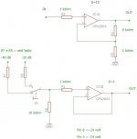
In attach you can find a simple circuit where you have the possibility to reduce by 20 dB or 40dB the signal you need to check.
Also, the input impedance of this circuit is high; if you need to check a signal from anode you must put a 10nF in series with the R7 that is 1 Mohm to block the dc voltage.
The input with R5 is 100 kohm and is not enough but you can use this at the output of the amp because with 20dB of attenuation you can see until 20 Veff ( less or more).
In the upper part of the image there is also a simple signl amplifier 10 time, can be helpful.
The supply is +/- 24 vdc, with this voltage is possible to get an output signal around 12 Vrms with a low distortion .
Walter
Scarica programma
It comes from a guy in the University of Roma, the last update is 2014.
It is very complete, need some practice but is very good.
With tone generator and sound card you can have a good test set.
In this way you can check each stage and the performances; the only thing is to use a right signals.
Regardin the output fro sound card you can have a good amplitude to drive the amps.
The problem is the input of a sound car becaues it accept max 2 volts, normally.
In attach you can find a simple circuit where you have the possibility to reduce by 20 dB or 40dB the signal you need to check.
Also, the input impedance of this circuit is high; if you need to check a signal from anode you must put a 10nF in series with the R7 that is 1 Mohm to block the dc voltage.
The input with R5 is 100 kohm and is not enough but you can use this at the output of the amp because with 20dB of attenuation you can see until 20 Veff ( less or more).
In the upper part of the image there is also a simple signl amplifier 10 time, can be helpful.
The supply is +/- 24 vdc, with this voltage is possible to get an output signal around 12 Vrms with a low distortion .
Walter
Attachments
Last edited:
I have seen the Visual analyzer before,just not used it,I will try it.
And I will build the limiter I need one of those.
When I built my F6 amp I used the audioTester
Where you could se the H2 H3 H4 and so on,maybe I t can be useful to.
And I will build the limiter I need one of those.
When I built my F6 amp I used the audioTester
Where you could se the H2 H3 H4 and so on,maybe I t can be useful to.
Yes of course.
Another thing is to check the freq answer
If you have a 192 khz 24 Bit card you can see 96 khz of BW, and it is enough
But another very important test is the THD versus frequency so you can see the shape of THD.
The optimal will be an orizontal line at same level for the sweep from the low freq to the high.; normally in a tube amp the shape is similar to U where at low freq. and High freq, mainly due the O.Transf. , the THD increase.
It is important also to check these performances without feedback first; the BW must be the wider possible, this is a simptom of a good project (O.T. included of course)
Walter
Yes I do have 192khz 24Bit.
One question about the OPT,as I am from Sweden It is allmost natural that I buy from Lundahl and the http://www.lundahl.se/wp-content/uploads/datasheets/1663.pdf
Is pretty cheapish.On the datasheet it says max power at 30 hz 40watts maybe thats on the limmit maybe not as we lowered the current.But do OPT have any headroom?
Quote:
I think that is not necessary the partitor connected to filaments of KT77
It is better to have two sec. each one with 3,15-0-3,15 v 4 A with the 0 to ground.
6A3 Answer:
As I said earlier, if there is any noise/hum as a result of leakage from the filament of the KT77 to the KT77 Cathode, you need to replace the leaky KT77.
Adding center taps will increase the cost, but go ahead and use them. If the KT77 IS leaky, and the leak is from one side of the filament only, now you have the leakage of 3.15V, not 6.3V. In either case if you have leakage you will get hum, so the leaky KT77 will have to be replaced. With good KT77s, you can just ground one side of the 6.3V (non-center tapped).
In any case, do not forget to twist the filament wires, or the hum will couple to grids of the tubes, and other circuits and parts that go to grids.
Quote:
The 2,6 H, in my opinion is not necessary, it is not a S.E..
It is much better to increase the capacitance; this circuit has 460 volt and 50 mA so each KT77 dissipate 23 watt, it is a heavy job.
I think that most of the power is in full class A;
6A3 Answer:
The reason to use a choke in the B+ is so that you do not have to use so much capacitance in the first filter cap. The 100uF first cap
has 13 Ohms of capacitive reactance at 120Hz ripple frequency.
With 200mA load, that is 2.6V peak to peak ripple.
But any larger capacitance will cause Very Large Peak rectifier currents which may cause the B+ secondary winding to heat (Isquared x R loss in the secondary).
Just as a reminder, in Vacuum Tube Rectifier days, you would have a hard time finding a rectifier that is rated for 100uF input capacitor, and it would either be for a lower current than 200mA, or it would be for less than 300Vrms, or both, with such a large input capacitance.
But the issue of the B+ secondary over heating does not change, it is even worse, because the vacuum tube rectifiers had a voltage drop (you can look at that voltage drop as a series resistance, which is far lower for solid stage diodes).
Quote:
it is possible to check with a cathode resistor that I suggest to be at 1 ohm/ 1 watt, in this way it acting as fuse in case some power tube go wrong.
For 10 ohm, as David Manley did, it is better to put a capacitor in parallel of 220 uF /25 Vdc.
6A3 Answer:
A 1 Watt 1 Ohm Resistor can take 1 Amp all day long (yes it will be too hot). But it does not make a good fuse for a KT77, the KT77 or the output primary will give up long before the 1 Ohm resistor.
A 10 Ohm resistor in the KT77 cathode will reduce the gain of the KT77 by Less than 1 dB. It is fine the way it is. And 50mA will give 0.5V, which can be accurately read by an old VOM that is in good shape.
A 220 uF bypass capacitor is 6 Ohms at 20Hz. Not a great bypass for 20Hz.
Quote:
About the ECC82 I think that 22K on the cathode it is an high value for the type of tube used in this point
6A3 Answer:
The ECC82 grid voltage is high on purpose; it is connected to the input triode plate. That is so that the voltage of the cathodes of the ECC82 will also be high. With high voltage cathodes, the common cathode resistance can be large (22K).
The 22k is a Pseudo Current Source. It is not perfect, so the unbalanced plate loads of 33k and 39k make up for it.
Lowering the 22k to a lower value will imbalance the plates even further, and will reduce the gain of the tube (it already is less than 1/2 of u (Mu) because of the cathode coupled splitter.
It was already mentioned that Ryssen was interested in using a solid state current source, which has much higher impedance, but the same voltage and current as the 22k (and same effective quiescent resistance as the 22k).
I like cathode coupled splitters, but do use solid state current sources and matched plate load resistors (each man has his preference; both can work well).
Last edited:
Spme answer
1- the best way to supply the filaments on the types like EL34 are ac with zero central to ground, this is my opinion.
The problem about hum is not so heavy because with a good selection done by the vendor is difficult to get this issue.
2-The power supply, in my opinion must be robust so a high reserve of Joule will help with dynamic signals; in this case I suggest to reach the 470 uF/1000 uF channel.
To solve the peak when there is power in is very simple; if you put a NTC 10/15 ohm-2/3 A in series with primary you are very safe ; within 20 second (less or more) it goes to 0 ohm and all works perfect, no trouble with trafo and bridge.
3- I use 1 ohm 1 watt as monitor of the current and fuse, in some case it help. Is not true that it takes long time, it blown rapidly.
Regardng the bypass on 10 ohms it is not important to get that impedance at 20 Hz, in every case you can't put it of course.
4- Regarding the ECC82, I have checked the voltage starting from 335 vac and it is high, there is about 10 mA ( around 5 mA /section) flowing in the ECC82 that take the cathode at 220 vdc ( less or more), in this case is better to elevate the filaments; I think there is an error on schematic.
The referred filaments are for signals tubes and the other secondary for KT77 with a zero central connected to ground .
So the current fot signal tubes is 6,3 Vac 2A
for KT77 two secondary 3,15-0-3,15 5 A each
In my opinion
The setting of CCS, I think, must be checked respect the voltage on anode of ECC83 so it is better to check the input stage alone, in this way is possible to understand how much voltage are on anode of 83.
Walter
Walter
Yes I do have 192khz 24Bit.
One question about the OPT,as I am from Sweden It is allmost natural that I buy from Lundahl and the http://www.lundahl.se/wp-content/uploads/datasheets/1663.pdf
Is pretty cheapish.On the datasheet it says max power at 30 hz 40watts maybe thats on the limmit maybe not as we lowered the current.But do OPT have any headroom?
Maybe it wont give more that 30-35w anyway.
Heres an examle of a 25w amp that runs on 400v
I see that photobucket have blocked the pic of the schema,it never happend before.I will write the and ask why,they want 399$ to unlock it....
If any one wants the schema P.M me your e-mail and I´ll send it.
I was thinking the trafo on the schema says to be 335vAC x 1.41 = 472v !! and that is with load,unloaded at startup I think I´m gonna have to use more that 500v rating on the e-lyts...😎
If any one wants the schema P.M me your e-mail and I´ll send it.
I was thinking the trafo on the schema says to be 335vAC x 1.41 = 472v !! and that is with load,unloaded at startup I think I´m gonna have to use more that 500v rating on the e-lyts...😎
Quote: waltube:
1- the best way to supply the filaments on the types like EL34 are ac with zero central to ground, this is my opinion.
The problem about hum is not so heavy because with a good selection done by the vendor is difficult to get this issue.
2-The power supply, in my opinion must be robust so a high reserve of Joule will help with dynamic signals; in this case I suggest to reach the 470 uF/1000 uF channel.
To solve the peak when there is power in is very simple; if you put a NTC 10/15 ohm-2/3 A in series with primary you are very safe ; within 20 second (less or more) it goes to 0 ohm and all works perfect, no trouble with trafo and bridge.
3- I use 1 ohm 1 watt as monitor of the current and fuse, in some case it help. Is not true that it takes long time, it blown rapidly.
Regardng the bypass on 10 ohms it is not important to get that impedance at 20 Hz, in every case you can't put it of course.
4- Regarding the ECC82, I have checked the voltage starting from 335 vac and it is high, there is about 10 mA ( around 5 mA /section) flowing in the ECC82 that take the cathode at 220 vdc ( less or more), in this case is better to elevate the filaments; I think there is an error on schematic.
The referred filaments are for signals tubes and the other secondary for KT77 with a zero central connected to ground .
So the current fot signal tubes is 6,3 Vac 2A
for KT77 two secondary 3,15-0-3,15 5 A each
In my opinion
The setting of CCS, I think, must be checked respect the voltage on anode of ECC83 so it is better to check the input stage alone, in this way is possible to understand how much voltage are on anode of 83.
Answers:
Just my (6A3) opinions:
1. Yes, grounding the Center tap on the 6.3V for the EL34, KT77, etc. reduces the effect of any hum or line noise, so get the center taps on the 6.3V and ground them (just in case there is filament to cathode leakage).
My vendor (Eurotubes) checks for hum, and various types of noise. I know them well, and I also know the person that made the multi-faceted tube tester used by Eurotubes, including the audio output to an amplifier and loudspeaker that checks for noise and hum.
I never had noise or hum problems with indirect heated cathode tubes, as long as the cathode was 'tied down', either by a low resistance, or by a bypass capacitor. That was true even in single ended amps, where there is no possibility of push pull cancellation of the filament leakage. Filament to cathode leakage is unlikely to be canceled in even in push pull, it would require the same mode, amplitude and phase to cancel). That is a completely different factor than cancellation of hum in the B+ due to push pull operation.
2. I agree that there should be more capacitance in the capacitor that directly feeds the output stage (the 2nd filter cap, right after the choke).
I was not talking about the in-rush current to charge the capacitors at power-up.
I was talking about reducing the peak rectifier currents on every alternation, after the amp has been on to be warmed up.
A 2 Henry choke has about 1500 Ohms of inductive reactance. A 1500 Ohm resistor would have too much DC drop. That makes a very efficient filter, with little loss of DC voltage.
The other advantage is the choke isolates the rectifiers from the 2nd filter capacitor. So use the choke, and then use higher capacitance at the 2nd filter capacitor. The input capacitor should not be real large, or the peak rectifier currents may be up to 10 times or more than the RMS current.
Most of my B+ power supplies use either choke input filtering, or have a small input capacitor before the choke (2 to 4 uF). After that, I use plenty of filtering of the B+.
That method keeps the power transformer B+ secondary much cooler.
3. It is quite possible that the primary winding of the output transformer will 'fuse' before the 1 Ohm 1 Watt resistor will. Depends on the output transformer. Resistors are cheap, transformers are not. A good DMM can easily read the 50mV at 50mA, so 1 Ohm is OK, just not to be trusted as a fuse.
Since a 10 Ohm resistor will only lower the gain by less than 1 dB, it does not really need a bypass cap, and it will have a flat frequency response from DC to whatever very high frequency the resistor's inductance is a factor, which is well beyond audio frequencies for either comp, film, metal, or non-inductive wire wound resistors.
4. Yes, I agree, the ECC82 filaments are the ones that should be elevated.
A current source in the ECC82 common cathodes, allows the use of precision matched resistors in the plate loads, and lowers 2nd harmonic distortion. It also solves the problem of getting the amount of current in the tube to be higher, but without having a small impedance on the common cathodes; which using less than 22k Ohms as the common cathode resistor does.
If there is a current source in the plate of the ECC83, that will increase the gain, and lower the distortion.
I agree, the plate voltage of the ECC83 should be checked before connecting it to the ECC82 grid.
However, if there is a current source in Both the ECC83 plate, And a current source in the ECC82 common cathodes, it makes it harder to do tube rolling. These 2 stages are DC coupled. Tube rolling of different manufacturers of ECC83; and different manufacturers of ECC82 should work.
But that might make voltages go all over the map when trying out a 5751 input triode; and either a 6CG7, or a ECC99 phase splitter (in place of the ECC83; and ECC82 respectively).
Changing tubes with different u (mu), rp, and transconductance does not work well when the 2 stages are DC coupled and with Either the resistors of the original circuit, Or current sources in both the input triode plate, and splitter common cathodes.
Last edited:

I got the pcb and the new schema,but the new schema is actually the same as before except that it has a relay for switching between Triode/UL.
I guess I´m going to collect parts then..
I guess I´m going to collect parts then..
An externally hosted image should be here but it was not working when we last tested it.
- Home
- Amplifiers
- Tubes / Valves
- KT77 P-P on a pcb from ebay...