In a weak moment I bought this pcb from ebay:
1 Stück vergoldet EL34 Push Pull Röhrenverstärker tube amp DIY PCB | eBay
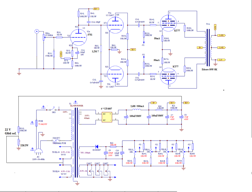
It has a 5751 as input tube and ECC82 as longtail splitter.
I am going to change the Ecc82 for a ECC99 or a 6CG7 and a CCS.
But is the 5751 any good for input tube for hifi?
I have seen some use 12AT7 as input tube,but I don´t know..
1 Stück vergoldet EL34 Push Pull Röhrenverstärker tube amp DIY PCB | eBay
It has a 5751 as input tube and ECC82 as longtail splitter.
I am going to change the Ecc82 for a ECC99 or a 6CG7 and a CCS.
But is the 5751 any good for input tube for hifi?
I have seen some use 12AT7 as input tube,but I don´t know..
I am going to change the Ecc82 for a ECC99 or a 6CG7 and a CCS.
12BH7 is another option.
But is the 5751 any good for input tube for hifi?
Yes.
jeff
Last edited:
the schema is at the bottom of the ebay page/link.
Make sure the output tubes's suppressor grids are connected to their cathodes.
Hopefully, it will be stable with whatever tubes you decide to use (and with whatever output transformer you decide to use). Negative feedback, different tubes, and different output transformers don't always mix (and this design uses negative feedback).
Yes, you very well may have to adjust the feedback resistor. You may also have to adjust the dominant pole series RC network.
That depends on the output transformer you use, and the tube types you use (i.e. 12AX7 versus 12AT7, etc.).
Your amp is Ultra-Linear (some negative feedback), has a dominant pole series RC network from the input triode plate to ground, and has a negative feedback resistor from the output transformer output tap to the input triode cathode network.
Output Transformers do not all have the same phase versus frequency. And they do not all have the same frequency response.
Tubes with different grid to plate capacitances; different plate resistance, rp; and other tube capacitances can also affect phase versus frequency.
The loudspeaker load on an amplifier also changes the phase versus frequency at the output terminals.
Three examples of what might affect the stability of your amp:
Changing the input tube type (it has a specific plate resistance, rp, that interacts with the dominant pole RC network that you have).
The output transformer you use.
The inductive and capacitive reactance versus frequency of your loudspeakers (very few loudspeakers present a resistive load at all frequencies).
Your major negative feedback path is from the output tap back to the input triode cathode network.
For Negative Feedback to work properly, the phase has to be nearer to 180 degrees, than to 0 degrees. It must do so properly for all frequencies where there is still gain in the amp (frequency response is not yet rolled off).
The dominant pole is C2 R4.
I can not read the value of R4 in the schematic.
but the schematic shows the C2 value as 100uF. It should be 100pF (not 100uF).
It goes from the input triode plate to B+. It is more common to put it from
the input triode plate to Ground, but either way works (so use the PCB as it is).
Wow, that schematic is hard to read, maybe it did say 100pF (which is correct).
Last edited:
I have a similar schema at home I´ll se if I can post it.
I will keep the input tube as is,but i see that ECC82 have Ri 7,7K and ECC99 is
2,3k and 6CG7 have about 7K.
So maybe it´s better to use 6CG7 instead of ECC99?
I will keep the input tube as is,but i see that ECC82 have Ri 7,7K and ECC99 is
2,3k and 6CG7 have about 7K.
So maybe it´s better to use 6CG7 instead of ECC99?
The schematic is simply.
But you need some instrument to check certain points of the project.
It is better to use the tubes type listed in the project.
The first stage is dc coupled with phase splitter so you must check if they work fine
The bias of the phase splitter is determineted by the input stage.
The input stage has a R-C in parallel to the anode load, this to limit the band. Maybe the O.T. trafo they provided has a resonance close to the audio frequency in this way they prevent oscillation when the feedback is connected; the feedback network is not frequency compensated.
I suggest you to buy a good O.T.
Have you listed the value of Vdc for each stage?
Remeber to put pin 1 and 8 of each power tube socket in short so you are sure that the g2 and cathode are connected
I suggest you to power on only the signal stages without power stage.
The check the points, p.e. the cathode of ECC82 must be at 4-6 volt over the grid of the upper section ( the one connected directly to the 12AX7, pin 1 or 6)
At power on don't connect the feedback; you have to check the phase of the ouput stage; it is simply, after power with the O.T. connected to the tubes and loudspeaker at the secondary, if you hear something like rumble ( it is increasing ) you must invert the cables (anode+g2) on primary from one EL34 to the other , leaving the central connected to Vdc.
The feedback can be connected in second time.
If you are able to get a generator and a good ac tester you will have the insurance to run in a right way.
Walter
My recommendation is get it working exactly as designed first.
Then modify it (the tubes are on sockets, not soldered in I hope).
Also, changing any other parts on a PCB too many times might destroy the PCB connections.
If you modify it first, you will never know how well it worked as designed.
Then you do not know if any mod improves it, makes it worse, or has no change at all.
Point to Point wiring is much more suited for modifying an amplifier.
Build this one, I bet it is very good.
You can do point to point for your Next amplifier.
A 5751 has a little more filament current, and 6CG7, 12BH7 and ECC99 have increasingly more filament current. Is the power transformer rated for it?
And why would you elevate the EL34 (or KT77 filaments)? Their cathodes are only 10 Ohms away from ground. If any filament leakage to the cathode is significant enough to cause hum, then you need to get working tubes. The 'elevation resistors will also lower the B+ slightly for the input triode.
Your hum, if any, will come from other areas of the circuit.
Question:
Is any particular tube good for Hi Fi?
If it is . . . then it is Only if it is in a circuit with parameters that are good for that tube model. Voltages, currents, plate load resistance, and drive impedance to the grid all affect how well even a 'perfect' tube works.
Let us know how well the amplifier works when you get it built.
The EL34 needs G3 Suppressor Grid connected to the Cathode. (Do not connect G2 Screen Grid to the Cathode).
I usualy order a custom trafo from torid.pl so that wont be a problem.A 5751 has a little more filament current, and 6CG7, 12BH7 and ECC99 have increasingly more filament current. Is the power transformer rated for it?
NO i think you missunderstod,I wrote I would use a CCS for the phasesplitter.And why would you elevate the EL34 (or KT77 filaments)? Their cathodes are only 10 Ohms away from ground. If any filament leakage to the cathode is significant enough to cause hum, then you need to get working tubes. The 'elevation resistors will also lower the B+ slightly for the input triode.
Your hum, if any, will come from other areas of the circuit.
Or is the filaments elevated on the schema?I havent seen it....
And the ECC82,I read on several forums that folks don´t like them.
Therefore I thoght as I have sevaral ECC99 and 6cg7´s I´d use them for phasesplitter.
I have seen several similar schemas with ex 6CG7.
Yes I´ll tell when It´l probably be a winter project as I have a SE amp to finnish first.Let us know how well the amplifier works when you get it built.
NoHave you listed the value of Vdc for each stage?
They gonna be on sockets.(the tubes are on sockets, not soldered in I hope).
Look at your schematic in post # 10.
The two 6.3V secondaries to the EL34 filaments are connected to a resistive divider that is connected to the last B+ filter Capacitor.
That is the elevated filaments that I am talking about in my post # 12.
The two 6.3V secondaries to the EL34 filaments are connected to a resistive divider that is connected to the last B+ filter Capacitor.
That is the elevated filaments that I am talking about in my post # 12.
If you replace the common cathode resistor, R9 with a CCS, then you have to change the plate load resistors in the splitter.
They are 33k and 39k, they are unequal to roughly compensate for the 'imperfect current source', R9.
With a CCS instead of R9, you have to make the plate load resistors of the splitter to be equal (i.e. either 2 each 33k, or 2 each 39k resistors).
They are 33k and 39k, they are unequal to roughly compensate for the 'imperfect current source', R9.
With a CCS instead of R9, you have to make the plate load resistors of the splitter to be equal (i.e. either 2 each 33k, or 2 each 39k resistors).
- Home
- Amplifiers
- Tubes / Valves
- KT77 P-P on a pcb from ebay...