Good day, tubers!
I've done a lot of reading on this forum, very informative. This is the first time I've posted to any forum, ever.. so if I am posting in the wrong section, or doing something otherwise incorrect, let me now.. I'll rectify the issue.
To the matter at hand.
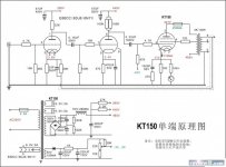
I will be constructing an amplifier based on the infamous Mikael KT88 SE schematic that seems to be a favourite schematic to build. I want to used KT150 tubes. My knowledge of electronics theory is limited (relating to valve tech) but I'm confident with a soldering iron, as well as following basic safety guidelines.
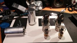
I've collected most of the primary hardware (PTrans, Tubes, Tube Sockets, Motor Run Caps, Chassis) but I will need some guidance from you lot, who's collective experience is a huge asset. I'm not sure where to start with my questions, so I'll just start..
Let's get the ball rolling.
I've done a lot of reading on this forum, very informative. This is the first time I've posted to any forum, ever.. so if I am posting in the wrong section, or doing something otherwise incorrect, let me now.. I'll rectify the issue.
To the matter at hand.
I will be constructing an amplifier based on the infamous Mikael KT88 SE schematic that seems to be a favourite schematic to build. I want to used KT150 tubes. My knowledge of electronics theory is limited (relating to valve tech) but I'm confident with a soldering iron, as well as following basic safety guidelines.
I've collected most of the primary hardware (PTrans, Tubes, Tube Sockets, Motor Run Caps, Chassis) but I will need some guidance from you lot, who's collective experience is a huge asset. I'm not sure where to start with my questions, so I'll just start..
- Will the 6N1P have enough output voltage to drive the KT150's to a reasonable level?
- If the 6N1P doesn't have the drive.. can I incorporate a 6SN7 preamp stage into this design? (I'd love to do this regardless)
- Would 3k Hammond SE OPT's be appropriate for this design?
- Are there any obvious changes that I would need to make to this design in order to use KT150's? (I've thought about making a selector switch to allow the use of KT150/KT88/6L6)
Let's get the ball rolling.
Attachments

Chicken. This:
An externally hosted image should be here but it was not working when we last tested it.
Unfortunately canadatubedude, your pic did not load properly.
With big tubes as expensive and rare as these, some form of delay circuit in the high voltage side will be very worthwhile.
I have a pair of KT150, but haven't put them to use yet.
Edit. Added a schematic I found that might help you.
With big tubes as expensive and rare as these, some form of delay circuit in the high voltage side will be very worthwhile.
I have a pair of KT150, but haven't put them to use yet.
Edit. Added a schematic I found that might help you.
Attachments
Last edited:
Like schematic. How many milliamps will a KT150 pull through the output? Any output xmers recommended?
Like schematic. How many milliamps will a KT150 pull through the output? Any output xmers recommended?
If you look closely at the schematic, there is 110mA current being passed by the KT150, and the output transformer is a 3kohm 30watt unit.
I plan to incorporate a "standby" switch that will allow me to heat the filaments before applying HV to the tubes. I'll draw up a schematic of the entire circuit sometime soon, and post it (if I can figure out how to do it correctly). I've already purchased components for this thing, so it's going to be built. I just want more input from you knowledgeable folks before I get too involved and do something completely wrong that will nuke my components, or not give the best performance possible.
..Thinking of having a 6SN7 linestage built right into the chassis (will be a large chassis) with the option to bypass and go direct to the 6N1P (assuming I use the Mikael schematic). I want versatility.
I'll be sure to post the entire build on here once things get going.
Thanks for the responses so far.
Cool. It looks like the drive requirements are pretty modest for a KT150 though. An additional linestage probably isn't going to be necessary at all. You'll just end up throwing gain away in the volume control.
But far be it from me to try and talk anyone out of adding extra tubes 🙂 I've done the same when I had an extra large chassis.
But far be it from me to try and talk anyone out of adding extra tubes 🙂 I've done the same when I had an extra large chassis.
I haven't seen any curves for a KT150 in Ultralinear, but looking at the KT88 curves, I'd guesstimate you'll want to bias around ~40-45V. That should be manageable for a 6N1P with a 2V input. KT150 (pentode mode) has an input capacitance of 20pF according to the data sheet and this will be a little higher in Ultralinear, but not enough to roll off HF.
That said, there are much more knowledgeable people on the forum and you should get a second opinion, too!
That said, there are much more knowledgeable people on the forum and you should get a second opinion, too!
Update
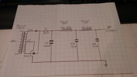
I'd like to drive the KT150's with 6SN7's. I've come up with the following layout for the components.
First image is assuming only SS rectification.
Second is assuming valve rectification, or perhaps being able to select between valve/SS rectification.
There will be a choke positioned at the front left corner, in front of the PTX. The two motor run caps in front would be mounted under the chassis with a turret board holding all the PS bits and bobs.
I'm still working out a circuit. There's another thread on here that discusses using one 6SN7 to replace the 6N1P. I figure with two, using both sides of the 6SN7 following one another, I could get the level of gain I would need to push the KT150's.
Opinions? Critique? Am I anywhere near a workable idea?
Discuss..
Attachments

This link may help you with your turn on delay for the high voltage.
Audio ratbag: HV delay using two DPDT switches
I have often used a glue called Goop to attach motor run caps. The bond is strong enough to easily hold the weight of the caps but not strong enough that the bond cannot be broken with a reasonable amount of force. Goop is usually available at Home Depot or Lowes. I am not sure if it is available in Canada.
Since your KT150's are so expensive, perhaps you could consider getting the amp working with a less expensive octal tube and then substituting your valuable KT150's.
ray
Member
Joined 2009
Paid Member
Why do you want hv delay? Waiting for the heaters to get hot just ensures that you'll put a big current spike through the tubes when the B+ suddenly comes live. At these voltages Cathode stripping is just an old wives tale and shouldn't be a worry.
I can wire up the HV delay with a standby switch, that's not a problem. If using valve rectification the normal valve delay should be sufficient. SS rectification is a different beast, that will need a standby switch or delay.
Anyone have a link to a schematic for a dual SS/Valve rectifier PS circuit (switchable) ?
I'd like to run a 5U4 and also internal UF4007 diodes, and be able to switch between the two. I'll have to have a smaller first capacitor after a valve rectifier, I think 100uf will be too much for a 5U4. My motor run caps are all 100uf currently.
I have all the parts for a PP 807 amp and would love to use the KT150 just because they look so dang cool. To pricey for that though. Good luck with your build.
No need for that . Just buy one of those empty octal sockets, the one that is just the plastic base and hollow pins. Then you buy the SS rectifier of your choice, I would think you would want some Hi voltage Schottky. the 3A x 1200v are about 3.00 a piece. Then wire them into the socket pins. You might have to solder some 18awg solid wire to the to220 rectifier pins to be able to do that. If I am not mistaken wire from pin 4 to pin8 and pin6 to pin8, if your tube rectifier is wired with Pin 8 to the filter.. Of course, make sure your rectifiers are properly oriented. So, if you want to go SS just pop the SS socket in and you are good to go. cheers, 808.I'd like to run a 5U4 and also internal UF4007 diodes, and be able to switch between the two. I'll have to have a smaller first capacitor after a valve rectifier, I think 100uf will be too much for a 5U4. My motor run caps are all 100uf currently.
I'd like to drive the KT150's with 6SN7's. I've come up with the following layout for the components.
First image is assuming only SS rectification.
Second is assuming valve rectification, or perhaps being able to select between valve/SS rectification.
There will be a choke positioned at the front left corner, in front of the PTX. The two motor run caps in front would be mounted under the chassis with a turret board holding all the PS bits and bobs.
I'm still working out a circuit. There's another thread on here that discusses using one 6SN7 to replace the 6N1P. I figure with two, using both sides of the 6SN7 following one another, I could get the level of gain I would need to push the KT150's.
Opinions? Critique? Am I anywhere near a workable idea?
Discuss..
You have a mighty tube there,
Because it is a pentode you will not mind EL34 as a sweet powerfull driver (which can be choke fed, regulated sink etc.) and an ultralinear or even better a cathode feedback output.
The 6SN7 can drive it , parallel it and drive without GNF to get enough gain.
Q: are you installing a power supply choke or SS regulator?
Member
Joined 2009
Paid Member
I don't think it does and you're better off without it.SS rectification is a different beast, that will need a standby switch or delay.
- Home
- Amplifiers
- Tubes / Valves
- KT150 SE based on Mikael's KT88 Schematic