Hi Bench Baron,
I've used 3 power supplies for B+ to be exact. The amplifiers PSU, the 19"rack PSU and another 450 Volt breadboard PSU. Oscillations occur with all three PSU's.
I checked all PSU's with a scope for hum, noise, etc.. The same goes for the negative voltage, a CCS current sink and the double DC heaters for the drivers.
In the current setup (looking for the source of oscillation) these supplies are not powered at all.
It's not the power supply (I would almost wish it was, so I could fix it).
I will now run some test according to the suggestions made earlier.
Regards, Gerrit
Since this is a safety issue, other questions arise. A more complete schematic would help the diagnosis. Racks, their groundings, power supply groundings and their inherent loops are all fair game.I tried grounding one of the output transformer’s wires to ground. Grounding / not grounding one end of the output winding makes no difference.
Al good fortune,
Chris
The answer to that is something called squegging
https://en.wikipedia.org/wiki/Squegging, as I said don't rule anything out until your sure. The speaker has a peak in impedance at around 1-2KHz so that will be your frequency defining component. Why you have positive feedback is less clear particularly in triode mode. I have had squeaks if a say a plate resistor is not soldered properly so check your soldering too in case you have a small arc. I would like to see some photos...
https://en.wikipedia.org/wiki/Squegging, as I said don't rule anything out until your sure. The speaker has a peak in impedance at around 1-2KHz so that will be your frequency defining component. Why you have positive feedback is less clear particularly in triode mode. I have had squeaks if a say a plate resistor is not soldered properly so check your soldering too in case you have a small arc. I would like to see some photos...
An exact resistance test on the output transformer may not reveal a single (or more) shorted turn (out of several hundred) that could mess with the leakage inductance, all it requires is a little gain to excite and off it goes into resonance;... however in such situations I would take a step back and switch all off.
Disconnect all o/p tranny primary/sec leads and start injecting a low AC 50Hz volts (2V) on the secondary(ies) and measure the volts/current on each step-up noting the ratios on each winding, primary to each screen etc.. Tabulate them. That is the standard check for a transformer with shorted turns. Remember, to use a low AC voltage as the step up for example 20:1 or higher can give excessive primary side voltages, despite a shorted turn having a very high leakage inductance, but the increased current way below the level of core saturation will be noticed.
A DVM doesn´t settle accurately when measuring the resistance when inductance is present.
It may be embarrassing to have such a situation when I look at the complex innards of my 500W tube amp, and others, but be assurred all of us have been through these problems sometime, beit mains trannies too.
Often simple things i.e getting the phase wrong on a dual trace scope when my collegue forgot to push out the CH2 invert button out. So be it.
Take care
Bench Baron

Hi Bench Baron,
1. I get what you mean. But I cannot believe all three (!) power supplies would be oscillating identical.
2. I already tried lowering the grid leak resistors to 50K, it's mentioned in my first post. It makes no difference.
3. The valve socket wiring is absolutely OK and identical to the other channel. All voltages and currents measure OK and identical to the "good" channel.
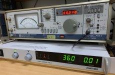
4. I use the Xantrex PSU so I can vary the B+ and stay on the safe side.
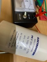
5. I just tried adding a 200 uF capacitor to the B+, but there is no difference. Actually the cap measures 190 uF.
Regards, Gerrit
1. I get what you mean. But I cannot believe all three (!) power supplies would be oscillating identical.
2. I already tried lowering the grid leak resistors to 50K, it's mentioned in my first post. It makes no difference.
3. The valve socket wiring is absolutely OK and identical to the other channel. All voltages and currents measure OK and identical to the "good" channel.
4. I use the Xantrex PSU so I can vary the B+ and stay on the safe side.
5. I just tried adding a 200 uF capacitor to the B+, but there is no difference. Actually the cap measures 190 uF.
Regards, Gerrit
Attachments
Here are the first results from my testing with a Zobel:
The OPT has a 4 Ohm and an 8 Ohm tap on the secundary winding. I have a 4 Ohm (3-way) speaker connected to the 4 Ohm tap. (Note: changing polarities on either or both ends did nothing).
Then I tried the Zobel option:
a. 10 Ohm with 2.2 uF -> oscillation at 1200 Hz.
b. 10 Ohm with 2.7 uF -> oscillation at 1166 Hz.
I tried smaller capacitors as well, but the oscillation remained and was then somewhere between 1550 and 1200 Hz..
I tried a small choke, and as expected the frequency increased somewhat.
So the oscillation's frequency is affected by the Zobel. The voltage needed to start the oscillation varied 5 to 20 volts; with the Zobel I needed a slightly higher voltage to start the oscillations. But it still oscillated, loud and clear.
Eureka?
With a value of 10 Ohm across the 8 Ohm tap there were no more oscillations! No capacitor! I could go from 300 to nearly 600 Volts without oscillation. I then tried other resistor values. 12.2 Ohm was still OK, but 14.4 Ohm would cause oscillation with a much higher B+ of 580 Volt. (Note: this is not a realistic use case, because with a 53 Volt negative grid voltage the total plate current is a lot more than 300 mA. In my "real" setup the current will be fixed around 100 mA per tube with an autobias board.)
I'm not sure what may be the conclusion from these tests. What do we learn from this empiric evidence?
Regards, Gerrit
Hi Bench Baron,
In the first post I already wrote this:
"I checked the OPT using a 1 kHz. signal on the 4 Ohm tap, measuring the amplitude and phase on the primary windings of the transformer. The phase measures OK for each side / tube and the amplitude on the UL tap is lower than on the plate tap. See image attached. All measurements are according to the label on the transformer (see attachment). I checked the other channel’s transformer as well, and the results are similar / identical."
Of course transformers will never be 100% identical, but the windings definitely are not mixed up, not inside the transformer and not in the amplifier's wiring.
I also wrote somewhere that I tested without any other equipment attached. Just the amplifier (using it's own PSU) with a grounded power socket and a speaker. Of course the amplifier has a proper PE ground with 10 Ohm to the PSU/audio ground. I checked this many times (even today) and it's still 10 Ohm.
Regards, Gerrit
Since you don´t need the 10 ohm across the other transformer, I´ll give you one guess 🤣I'm not sure what may be the conclusion from these tests. What do we learn from this empiric evidence?
I´ll bet you a whole imaginary box of ½liter IPA´s (or Duvel´s since you´re from the Netherlands) that the problem is my first suggestion,
even if you were "too lazy" to try it out: Even if you can´t seem to measure any immediate difference, there´s something
wrong with your output transformer.
I know, it´s hazzle, but only way to be sure/claim warranty is to switch the two transformers.
If everything else was swapped and nothing changed, swapping the transformer is the obvious only remaining thing to do.
Yet, I have a feeling getting another transformer will not fix this.
Yet, I have a feeling getting another transformer will not fix this.
Toroidy trafos may have some coupling issues, have experienced something similar with a 3.2k (TTG EL34 SE model) Its some kind of capacitive coupling between plate windings and secondaries, try swapping the output leads ground (without NFB in place), solid grounding, and with a 10R resistor (some low impedance but not a dead short ground), and reducing tube bias, have seen also a kind of inestability around 100mA in my case, I think its quasi saturating or some thing happening around the transformer, I think that can also mess with the phase linearity, also try changing ground routing, it has to be a daisy chain from the most consuming to the least (being the Main supply ground then the output tubes cathode ground returns, then the driver stages then the vias ground return and previous VAS stages), you can also put a boucherot cell at the primary of the OPT to swamp parasitic oscillations happening in the plates/OPT.
Hi Boydk,
It’s not that I’m lazy, but switching transformers is at least a day’s job. Space is tight, wiring was done with a lot of care and safety measures, including shrinkwrap. Removing all this and rebuild it is possible, but only a a last resort.
First I want to know why the 10 Ohm resistor may have the effect it evidently has.
Regards, Gerrit
Simply because its more like the resistive only load removing more of the speakers resonance. You've not solved the issue.
ok is there a gain difference between the two channels? So use the resistive speaker load. Apply 1KHz tone say 5Vpp to each of the output grids through the coupling cap C2/C3. Measure at speaker terminals. Measure gain and phase for all 4 tubes. Any problems with phasing etc I would think should show up. You must always load the outputs if HT is applied.
Last edited:
I don't know the roor cause, just thinking loud. Oscillation is always caused by positive feedback. There is a hidden feedback somewhere in this apparently open loop circuit.
Hi Baudoin0,
I may try this measurement with the 1 kHz. signal. I gues I will need a phase splitter for this. Perhaps tomorrow, if I can find the time for this.
I can measure this with a (RMS) millivoltmeter.
Regards, Gerrit
I may try this measurement with the 1 kHz. signal. I gues I will need a phase splitter for this. Perhaps tomorrow, if I can find the time for this.
I can measure this with a (RMS) millivoltmeter.
Regards, Gerrit
Toroidal OTs generally have excellent magnetic coupling and low leakage inductance.
But the problem is huge primary capacitance (typically in the nFs, so roughly 10 times larger than with E-I- core types) as well as large primary to secondary capacitance. Reason is the close proximity of the windings and the conductive core.
Together will the speaker inductance the OT capacitance reflected to the secondary forms a resonant circuit.
Last edited:
For improved stability with UL operation, see the circuit supplement pages here:
https://frank.pocnet.net/sheets/084/k/KT88_GEC.pdf
https://frank.pocnet.net/sheets/084/k/KT88_GEC.pdf
Well I have done dome simulation with a real speaker load. No I cannot see instability which is what you would expect. However if you swap the screens or plates over then I do get oscillation as you have described but only with a real speaker. Is it possible that your toroidy transformer has the colours wrong. Why don't you just try and see if that what it is.

- Home
- Amplifiers
- Tubes / Valves
- KT150 Push-Pull audio frequency oscillations