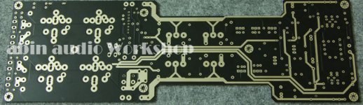
And this is The Bom (Build of Material)
http://www.diyaudio.com/forums/solid-state/31077-krell-ksa-50-pcb-802.html
Looks Post 8018
http://www.diyaudio.com/forums/solid-state/31077-krell-ksa-50-pcb-802.html
Looks Post 8018
Hi Abin
i look once again some schematic, bom jan and pinkmouse & pcb
i realise there isnt 2pcs X 22uf / 16v in your board
i give you jan & al (pink mouse) BOM (build of material)
Jan Dupont - Pavel Dudek give this 22uf on the board after a long
discussion. Even didnt look at the bom there is 2 pcs X 22uf / 16 v
on AL Boards
in ksa 100 thread i look they change this electrolyt 22uf/16 to mkp
1 uf (mundorf Mcap)
my question is
- why you remove this caps ?
- if i want to use this caps where the best place for it ?
the 22UF that part necessity has not used it.
And this is The Bom (Build of Material)
http://www.diyaudio.com/forums/solid-state/31077-krell-ksa-50-pcb-802.html
Looks Post 8018
After perfect edition PCB comes back, I will complete BOMs.
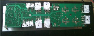
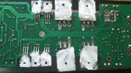
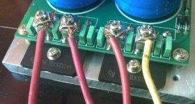
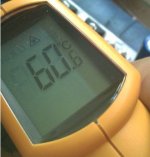
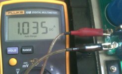
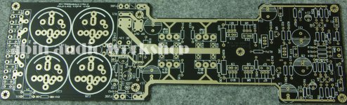
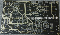
Today's test result, each pair of tube's operating current is the 1A,1 hour later operating temperature is 60C。
Attachments

Hello.
KSA50 already built one🙂 Pcb krell ksa 50 - Do It Yourself - Forum Audio - Audiostereo.pl # k
I would like to make a second guest gxcnabin.
Can I buy a set of PCBs stereo?
Piotr. ( piotr_michalski1@o2.pl )
I apologize for my language - google translate😉
KSA50 already built one🙂 Pcb krell ksa 50 - Do It Yourself - Forum Audio - Audiostereo.pl # k
I would like to make a second guest gxcnabin.
Can I buy a set of PCBs stereo?
Piotr. ( piotr_michalski1@o2.pl )
I apologize for my language - google translate😉
the 22UF that part necessity has not used it.
heres the link from Jan Dupont himself look post # 48
http://www.diyaudio.com/forums/solid-state/31077-krell-ksa-50-pcb-5.html
Pavel:
Thanks for correcting me 😉
I must learn not to read and write when I'm tired 🙁
Bratislav (and others):
The V-I limiter was put in as an additional options for those who would like some kind of protection.
Don't like it ??? Don't use it 😉
The output coil are shown in the schematic for those who will build this amp with new high freq. transistors....
I'm not sure how it will respond to modern components, so better be safe than sorry 😉
And again: Don't like it ??? Don't use it 😉
Please keep the comments comming😀
You're right ABIN, will be OK without 22uf
Last edited:
Today's test result, each pair of tube's operating current is the 1A,1 hour later operating temperature is 60C。
Hi gxcabin , what voltage are you Running at?
My tests was done with +-30V and 1.5A (750ma per device).
My heat sink is 0.33C/W
30V at 1.5A calculates to 45W ,so total heat is 90W per channel.
90W on 0.33c/w = 29.7C increase.
Room was 25C and I measured 55C on the heatsink (device = 60C) after about 30 minutes.
750mA per device calculates to 3Amp total = 36W into 8ohm = 14W into 4ohm
Is my math correct? Do I understand ksa50 calculations correct?
Hi Abin
Hi Tangmonster
In other thread 330uf replace by 47uf, 620p still there
(pink mouse use osciloscope for this)
so what decision you will take guys
btw abin, why you give 100p before ?
Hi! tangmonster
620P changes 330P .
100P to be possible not to use.
Hi Tangmonster
Hi gxcabin, I changed my 620P to 470p i am sure 330p will also be fine. -3db is around 100Khz with 470p.
As soon as i have it up and running i will do tests with the oscilloscope and check wave forms. i might then leave out 100P or make it higher value.
Thanks!
In other thread 330uf replace by 47uf, 620p still there
(pink mouse use osciloscope for this)
so what decision you will take guys
btw abin, why you give 100p before ?
Hi gxcabin , what voltage are you Running at?
My tests was done with +-30V and 1.5A (750ma per device).
My heat sink is 0.33C/W
30V at 1.5A calculates to 45W ,so total heat is 90W per channel.
90W on 0.33c/w = 29.7C increase.
Room was 25C and I measured 55C on the heatsink (device = 60C) after about 30 minutes.
750mA per device calculates to 3Amp total = 36W into 8ohm = 14W into 4ohm
Is my math correct? Do I understand ksa50 calculations correct?
LUKE use 0.32c/w heatsink with 1,5A, He tried 1,9A then back again to 1,5A
Hi Abin
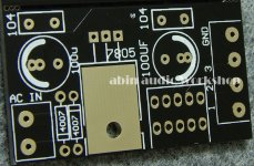
1. pls give me relay specification in your board
2. how much voltage for caps (4.7, 47 & 220) near relay ?
best regards
1. pls give me relay specification in your board
2. how much voltage for caps (4.7, 47 & 220) near relay ?
best regards
I also asked gxcabin about the relay
His email said OMRON G2R-2 DC12V
SNAP!
Is OMRON G2R-2 DC12V, has the question?
The UPC1237 part, 1K the 2W resistance may use 750R 2W

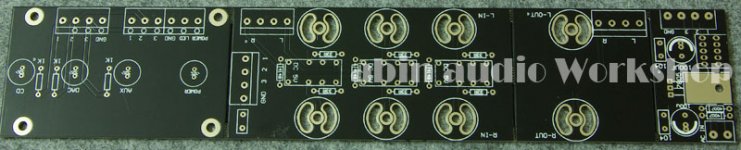
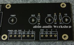
12AX7 \ 12AU7 vacuum tube Pre-amplifier also completed.
Attachments
-
 IMGP3231.JPG72.1 KB · Views: 220
 -
 IMGP3232.JPG54.9 KB · Views: 84
 -
 IMGP3235.JPG193.8 KB · Views: 85
 -
 IMGP3250.JPG129.9 KB · Views: 77
 -
 IMGP3249.JPG144.7 KB · Views: 76
 -
 IMGP3236.JPG123.8 KB · Views: 88
 -
 IMGP3251.JPG118.4 KB · Views: 79
 -
 IMGP3252.JPG173.3 KB · Views: 85
 -
 IMGP3253.JPG187.2 KB · Views: 88
WOW...simply beautifull 😀
Hi! CeeVee
Tomorrow I will go to the express company to consult, will answer you as soon as possible.
- Status
- Not open for further replies.
- Home
- Amplifiers
- Solid State
- KSA50 AMP(New production Live in...)