Just an idea.
You already have ducts below the heatsinks.
You could place ducts around the heatsinks and a fan behind them. Make the heatsinks shorter at the front and place a round curved plate in front of them.
The fans at the back blow air in the heatsinks, and it returns through the ducts below to the back of the amplifier.
With the dimensions you posted your heatsinks are too small to handle 130-140 watts per side.
An estimated guess is that the thermal factor of the heatsinks will not be lower than 0.35 C/W if mounted erect.
Placed horizontal it could be as bad as 0.50 C/W, at full bias they'll become hotter than 90 C. Even if the efficiency of the heatsinks remains intact, at 0.35 C/W they'll be +70 C.
Take a look at the Fischer SK163 heatsink and it's thermal factor graph (page 47) :
www.fischerelektronik.de/fischer/uploadfischerfcool/Fischer/A.1.5.pdf
Look Al, another Pink baby
jacco vermeulen said:Look Al, another Pink baby
All the ones best are! 🙂
Those little pink plastic spacers have exactly the right dielectric constant, as well as providing optimal vibration damping for the entire chassis/pcb assembly, they improve soundstaging, give more clarity at the top end, and produce at least an octave of extra bass at the bottom. You should be selling them for at least $300 a set Jacco! 😉
Al,
look deep into my eyes and repeat my words
" Jacco is a degenerate flunk, he can't even talk audio cattle into buying Halma beads "
look deep into my eyes and repeat my words
" Jacco is a degenerate flunk, he can't even talk audio cattle into buying Halma beads "
Re: 2000VA transformer
Hi Gaborela,
I ordered one of AudioHobby's transformers about 2 weeks ago also. It just arrived here in California on Saturday. It is quite impressive at about 6 1/2" diameter by 3 1/2" tall. I think it will fit in my chassis, but it definitely has a bigger footprint than the two 500VA torroids I was planning to stack in there.
Robert
gaborbela said:HI
I would like to ask a question from those people who orderd transformer fro the audiohobby guy if everibody receved it .
I orderd a transformer a couple weeks a go for the Krell clone but until now I did not receved yet .
I wrote some email to the him but he does not answer to me .
Just to be clear why I'm worried not just no answer , and no transformer , he closed his site and he close at the Audiogon site to .
Please let me know if you are in the same shue like me .
Thanks
Hi Gaborela,
I ordered one of AudioHobby's transformers about 2 weeks ago also. It just arrived here in California on Saturday. It is quite impressive at about 6 1/2" diameter by 3 1/2" tall. I think it will fit in my chassis, but it definitely has a bigger footprint than the two 500VA torroids I was planning to stack in there.
Robert
I can read that i have to do something to get the heat away, i think i will make the duct bigger so that my 80 mm fans fits that is no big problem to do that and then i have to do something get the fans invisible and still able to "breath" maybe a pull - push solution with 4 fans.
That would also give me the possibility of placing the topcover lower, and give the heatsink more "air".
As an alternative i could use 4 of those heatsinks and make a towerversion instead - there goes my WFD design..😀
That would also give me the possibility of placing the topcover lower, and give the heatsink more "air".
As an alternative i could use 4 of those heatsinks and make a towerversion instead - there goes my WFD design..😀
Hi,
re post6038,
black is better than a pale colour and better again than polished.
I read somewhere (maybe ESP site) that varnish is better than bad black. The site quoted a range of values for about five different black finishes and there were more surprises than just the varnish.
Black paint, if very thin, could be better than black anodise.
All the radiation amounts to only 10% of the total dissipation so losing a bit due to poor black will make little overall reduction.
However, using a horizontal sink with no forced cooling reduces the convected heat dissipation and then radiation becomes much more significant.
ROVSING said:there goes my WFD design
Sunglasses and a present once a month works miracles.
Re: 2000VA transformer
I ordered the "complete chassis" from him a couple of weeks ago and rx'ed last Monday.
I am like-wise still awaiting the transformers, but since they are being shipped from someone/where else(blue circle I believe) I am not worried as of yet...
gaborbela said:HI
I would like to ask a question from those people who orderd transformer fro the audiohobby guy if everibody receved it .
I orderd a transformer a couple weeks a go for the Krell clone but until now I did not receved yet .
I wrote some email to the him but he does not answer to me .
Just to be clear why I'm worried not just no answer , and no transformer , he closed his site and he close at the Audiogon site to .
Please let me know if you are in the same shue like me .
Thanks
I ordered the "complete chassis" from him a couple of weeks ago and rx'ed last Monday.
I am like-wise still awaiting the transformers, but since they are being shipped from someone/where else(blue circle I believe) I am not worried as of yet...
Off course - i haven't thought of that !
for the women who's got everything : 2 pieces of 500VA toroids fore her own personal Aleph - X (I happen to have PCB 's for that laying around - she can have them too) feminine colour - red with gold thanks to Pinkmouse - i'm sure she will be impressed😀
for the women who's got everything : 2 pieces of 500VA toroids fore her own personal Aleph - X (I happen to have PCB 's for that laying around - she can have them too) feminine colour - red with gold thanks to Pinkmouse - i'm sure she will be impressed😀
oops!
thanks to Kari - sorry pinkmouse and sorry Kari - maybe it's time fore me to get a little sleep😱
thanks to Kari - sorry pinkmouse and sorry Kari - maybe it's time fore me to get a little sleep😱
Which Way to Go?
I am at a cross road in my design. My internal chassis space is limited to 9" (22.86cm) H x 6" (15.24cm) W (square). These are maximum dimensions and I really need a little extra room in width to accomodate the transistor busses. Within that minuscule volume, I need to fit 2 500VA or 625VA transformers (damn, that surplus job from audiohobby is a tiny bit too big to squeeze in), supply caps and the main and driver boards.
Here is the dilema: I can use 2 500VA torroids and use 4 big cans, or I can use 16-24 parallel smaller caps and could use 625VA iron. That is my space limitation unless I have custom iron wound. I'm not sure one way is clearly better than the other, but I do wonder what you guys think? It seems that bigger iron is usually better, but large cans seem to have clear advantages in this kind of amp as well.
I'd like to add that those surplus A2 sinks I got from audiohobby maybe were not such a good deal after all. My "friend" the machinist finished the rest of the chassis parts and gave me the bill last week and my wife says I actually went pale looking at the invoice. She was a good sport though. After all shes gotten all the goodies for months. What could she say. Its the perfect WAF strategy.
K-amps- you still got those output pairs for sale?
If you can get a minimum of 50KuF per rail in, (i.e. four big caps), then go with two transformers, if not, one.
oops, I guess I wasn't very clear. I have room for two stacked trafos of either variety 500 or 625VA, but I need to choose smaller iron-bigger cans or bigger iron, muliple smaller cans. I also have been wondering about heat build up. The A2 had no ventilation slots in the top and bottom lids. I thought about adding some straight slots, but the machining cost is going to be ugly. For now I thought I would just try them first and machine later if they seems to be really hot. But it occured to me that the A2 had only one trafo and I will be using two, which means more internal heat. Is there any easy way to predict the extra thermal load from the additional trafo? Andrew? jacco? anyone?
Pretty chassis cost a pretty penny. 😱
Pretty chassis cost a pretty penny. 😱
niles said:
***
Is there any easy way to predict the extra thermal load from the additional trafo? Andrew? jacco? anyone?
Pretty chassis cost a pretty penny. 😱
Your final point is well taken and I fully agree.
I don't think that bigger xformers mean more heat, but that's just me. I have two 700 VA stacked one on another and they don't even get warm.
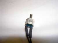
I have two of these "resistors" wich i would like to use to control fancooling on my krell - does anyone know an easy way - construction - where i can use them for this purpose ?
I do know that the hotter they get the lower the resistance become.
Each of them shall control one fan 12V 0,14A
Will a currentdivider do ?
I don't know on wich temperature the resistors reach zero but i could find out - putting it in the oven with a thermomethre attached mesauring the resistance at the same time.
Attachments
Pretty chassis cost a pretty penny.
If you're lucky you can have your local highschools (17-19years?) metalshopstudents weld something up for you and then add some coating for a symbolic fee and the cost of the material.
Just an idéa.
niles said:which means more internal heat.
Bigger transformers have a higher efficiency, means less losses.
A 500VA toroid constantly delivering less than 150 watts will not heat up significantly, stacking toroids is common practice.
Heat loss in toroids is important if the transformers are potted, but relatively also because thermal resins still have lousy thermal conductivity.
Heat from the transformers is the least of your problems.
Heat build-up from all components in the chassis is important. Thin steel chassis usually have venting slots, aluminium chassis often can do without because of much better thermal exchange.
ROVSING said:I don't know on wich temperature the resistors reach zero but i could find out - putting it in the oven with a thermomethre attached mesauring the resistance at the same time.
I have a LM317 circuit I use that's very simple. We only need to know the resistance at room temperature and at say 70-80 degrees C, and you can get that with a mug of hot water. This is only really to check that resistance decreases with temperature. Oh, and the voltage of your fans... 😉
Measure resistance in hot water
I would not do that, you could burn the isolation an the potting at the NTC-resistor. Just put it in heating water together with a thermometer. You could also mount the NTC at a Alu- bracket if you dont want to immerse the NTC under water. Check temp and resistance and make a temp/res. graph up to 100°C.
You will connect the resistor in series with the fan (if the NTC is built for the purpose). When heat sink is getting hotter the NTC´s resistance is getting lower, giving more and more current to the fan which will start at low resistance at the NTC (=hot heat sinks). But only if NTC and fan is chosen to match each other. Otherwise you need a transistor to take care of current to fan like a simple emitter follower ( NPN 1A 30-60V): one base resistor to GND (4k7 ?), NTC between base and Pos (12V), Collector to Pos, emitter to fan (pos/red) and fans neg/black to GND. But you must check it works properly before installing in chassis (full speed at ca 80-90°C ?).
Just some thoughts
Regards 😎
I don't know on wich temperature the resistors reach zero but i could find out - putting it in the oven with a thermomethre attached mesauring the resistance at the same time.
I would not do that, you could burn the isolation an the potting at the NTC-resistor. Just put it in heating water together with a thermometer. You could also mount the NTC at a Alu- bracket if you dont want to immerse the NTC under water. Check temp and resistance and make a temp/res. graph up to 100°C.
You will connect the resistor in series with the fan (if the NTC is built for the purpose). When heat sink is getting hotter the NTC´s resistance is getting lower, giving more and more current to the fan which will start at low resistance at the NTC (=hot heat sinks). But only if NTC and fan is chosen to match each other. Otherwise you need a transistor to take care of current to fan like a simple emitter follower ( NPN 1A 30-60V): one base resistor to GND (4k7 ?), NTC between base and Pos (12V), Collector to Pos, emitter to fan (pos/red) and fans neg/black to GND. But you must check it works properly before installing in chassis (full speed at ca 80-90°C ?).
Just some thoughts
Regards 😎
- Home
- Amplifiers
- Solid State
- Krell KSA 50 PCB